Ozi 206 sp

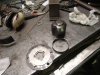
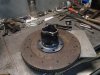
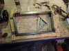
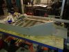
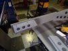
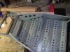
All the tubes are welded to the bracket first, the pics in post 14 show tacs but it is welded all the way around the base in the tac area.
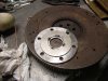
the crush tubes actually pass through the bracket and can be fused on the face side if you wanted.
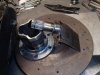
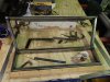
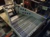
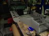
The assembly is then fitted with 2 bolts in the jig and 4 x 1" welds on the corners to fix it to the floor.
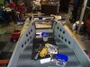
It also gets welded to the side panels externally as in pic 2 post 16
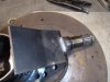
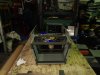
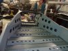
When the back goes on the tubes pass out through the mid way panel, this mid panel is then welded to the side panels.

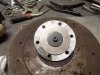
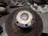
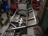
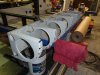
When the bolts pass through to attach the wheel bearing these are also doing the job of holding the bracket as it is clamped between the bearing assembly.

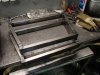
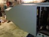
The tube bracket assembly is spreading the load through the whole upright not just one face because it is attached to the floor, sides , mid way, then into the very rear panel through the rectangle box.

Jim
 
Last edited:
Looks good Jim, How thick is the brake bracket? hard to tell in the photos but looks like only 3-4mm. What hubs/CVs are you using? Keep it coming will be following with great interest. 2-3 yrs, I might even get mine finished first.

Cheers Leon
 
Thanks leon

6mm on the bracket

Hubs and CV are 2010 Toyota Corolla.
Their is a 4 or 5 stud, went 5.
Front disk of the same car are fitted all round as well.

I wanted one doner, less messing.

Jim
 
Today I built the inner CV joints.
I have 2010 corolla drive shafts as they fit the wheel hubs.

My aim with all this stuff is to keep the match up as simple as possible.
I was not sure about how to match up to the 01E as the corolla has a splined shaft on its CV to go into their gearbox.

The other day I was working on a mid 2000 VW golf and I noticed the inner CV and flange was separate, somehow it was jointed I am presuming welded.

I went to the steel supplier and grabbed 4 bollard caps.

First thing was to make the base , I used a 50 cap to centre the SS cap that I have machined to a ring.
Once centered I clamped the SS ring and removed the 50.
I weld the SS ring on the inside, this becomes the locator on the 01E flanges.

I chopped the shaft of the end of the toyota CV, this leaves a 40mm dia spigot.
I then machined the center of the large disk to 40mm.

I machined a ring out of some steam pipe ,this fits between the main disk and the CV.
I tacked everything then put it in the lathe to check it then welded.
 

Attachments

  • P5300071.jpg
    P5300071.jpg
    197.1 KB · Views: 483
  • P5300072.jpg
    P5300072.jpg
    182.2 KB · Views: 488
  • P5300064.jpg
    P5300064.jpg
    200.7 KB · Views: 478
  • P5300068.jpg
    P5300068.jpg
    157.6 KB · Views: 503
Last edited:
The ring is welded to the base of the tripod joint and around the ring base.
It has a total of 550mm of weld.

I did some destruction testing prior to see if the CV material is not to brittle.
I hit it with a large hammer and also in the press, it survived.

Jim
 

Attachments

  • P5300073.jpg
    P5300073.jpg
    168.3 KB · Views: 484
  • P5300076.jpg
    P5300076.jpg
    155.2 KB · Views: 514
  • P5300078.jpg
    P5300078.jpg
    167 KB · Views: 490

Dimi Terleckyj

Lifetime Supporter
Hi Jim

If you want to do some destruction testing just give it to me.
I'm pretty good at destroying things.

Looking good mate.
Dimi.
 
It has been a while so time to update.

I spent days making tooling for a press brake I made years ago.
I made several press bars and former's ,I replaced the rams.

Before starting the chassis I made the front and rear members.
The front ,suspension steering hangs off, the rear the frame housing the engine assembly will couple up to.

The jigs are simply blocks of wood screwed to the table.

Required holes drilled working off the center line.
Crush tubes and locators are welded in.
 

Attachments

  • P6190001.jpg
    P6190001.jpg
    171.1 KB · Views: 459
  • P6190003.jpg
    P6190003.jpg
    168.7 KB · Views: 431
  • P6250005.jpg
    P6250005.jpg
    161 KB · Views: 450
  • P6260008.jpg
    P6260008.jpg
    192.1 KB · Views: 461
Last edited:
First panel is the floor then just build up from there.

Front members go in.
 

Attachments

  • P8240009.jpg
    P8240009.jpg
    125 KB · Views: 485
  • P8240010.jpg
    P8240010.jpg
    164.7 KB · Views: 465
  • P8260011.jpg
    P8260011.jpg
    163.5 KB · Views: 470
Front side panels.
The suspension brackets mount directly to the members

On the inside I made a panel ,then lightened and swagged.
 

Attachments

  • P8270015.jpg
    P8270015.jpg
    172.7 KB · Views: 499
  • P8270014.jpg
    P8270014.jpg
    146.4 KB · Views: 446
These panels rivet to the side off the rear member then to the side panels.
The seat lower section and part of the back will also be attached to the rear member.

I have never made a tub before so I keep thinking of the loads and how they need to transfer into the chassis.

The floor I wanted to stiffen.
I had to make some dies to get a very low profile hat shape, then I punched and swagged.

2 panels between the front members is fitted.
 

Attachments

  • P8270016.jpg
    P8270016.jpg
    137.7 KB · Views: 470
  • P8270020.jpg
    P8270020.jpg
    159.3 KB · Views: 522
  • P8270029.jpg
    P8270029.jpg
    170.6 KB · Views: 504
Anywhere you can see the back I use a solid aircraft rivet and other areas are steel structural on steel and alloy on alloy.

Doing the solid rivets is a 2 man job, one on the gun the other on the bucking bar.
 

Attachments

  • P8270023.jpg
    P8270023.jpg
    124.1 KB · Views: 485
  • P8270031.jpg
    P8270031.jpg
    143.7 KB · Views: 516
The side pontoons I made a jig to cut the panels with a trimmer.
I also have a timber jig to fold the radius on to get them all the same.
The large hole is for the fuel tank to slide into.

The outer sill skin will rivet to these.

It took a few saturdays to make the panels and about a day to rivet them all together to this point.

Thats it for the moment.

Jim
 

Attachments

  • P8270032.jpg
    P8270032.jpg
    143 KB · Views: 496
  • P8270034.jpg
    P8270034.jpg
    168.1 KB · Views: 508
Last edited:
Thanks Clayton.

You must have good eyes you can hardly see them.

The 206 has no roof so if it gets water on the deck it will drain through the joggles to the rear outlet.

Jim
 
Things are moving right along there Jim. I to noticed the joggles and wondered how you made them, are they just hammered in after you bent the panel up, that is how I have done light features in my panels. I see you are using a mix of steel and alloy panels, is that how the originals were constructed? As always the work is top class.

Cheers Leon.
 
Thanks Leon

The originals where a tube chassis sheeted in alloy.
I have always wanted to make a tub and this is my chance.

The joggles are made using an alloy bar 3/4 wide.
I milled a slot 1.6mm deep the width of the joggle.
I put the finished panel in the press brake with a strip of 1.6 sheet under it the width of the joggle, hitting with a hammer would work just as well.
Place the bar over the top and push down, its that easy.
I have a bunch of then for different jobs.

The sheeting is all 1.6 5005 alloy, I have etched it and it will get painted.
The etch does look like zinc coated steel.
The frames are ERW 50x25 1.6mm steel

Jim
 
Is the VQ30 what you are going to use? if so you won't be dissapointed, they are an awesome power plant. I have a Skyline Q35 with the 3 ltr VQ V6 and it is a heavy car but it can fly so in a small alloy car it will be a rocket.

Cheers Leon
 
Back
Top