S2's Build Thread

Scott

Lifetime Supporter
I am going to try super hard to make them fit

Hector,

I laid up a fiberglass shell on the lens, trimmed it on a bandsaw and cleaned up the edges a belt sander. Not pretty, but it will get the job done. If you look at the picture below, it appears to be a great fit.

jag1.jpg


However, in that orientation the beams would be pointed into the road 10 feet in front of the car. To determine the correct orientation I placed the headlight on a bench and I propped it up so that the bottom-most ballast was flat on the bench. Looking at the bulb, it appeared to be the correct orientation. I then laid the shell on the lens, ensured that it was positioned correctly and positioned a magnetic digital level on the longitudinal steel plate that I had bonded to the top of the shell. Once that was done, I zeroed the level and oriented the shell on the car so that it read zero.

jag2.jpg


As you can see you would need to significantly increase the height of the front of the nose to properly orient the headlight.
 
Last edited:
I am going to bench test them and see the exact beam orientation, I already have the lights and pig tails so it costs me nothing to do that , however based on your legwork looks like they will be pointing too low , which is a big huge bummer since the fit is sooo close. Thank you again for the leg work , super helpful . so, how about driving with the brights on all the time? I guess I will check that out as well, then will look into possibly reorienting them up somehow, probably not worth the trouble, but just thinking out loud.
 
I am a bit confused, the profile of the jaguar f type hood seems a little steeper than the Slc , I would have expected the light beams to be too high not too low. What am I missing?
 

Attachments

  • 2017_Jaguar_F-Type_Convertible_V8_R_AWD_Automatic_5.0_Front.jpg
    2017_Jaguar_F-Type_Convertible_V8_R_AWD_Automatic_5.0_Front.jpg
    291.7 KB · Views: 170

Scott

Lifetime Supporter
The left header has been moving along at a glacial pace, but the heatwave has sped things up. Using the icengineworks model as a guide, the first step was to cut, deburr, brush and tack weld both the left and right sides of the four primaries that cross under the pan. They were left loose in the the flanges on the heads and under the oil pan. Once that was completed the remaining two primaries on the left side were cut and tacked. As previously mentioned, the iceengineworks tack welding clamps are extremely useful during this process. Each runner was removed and finish welded on the bench.

1624931952311.png

Left primaries finish welded. The bulges where it might appear that the tubes aren’t concentric are where the tube steps up from 1-7/8” to 2”

The tubes running under the oil pan were kept long up to this point so they were reinstalled and after measuring ten times they were removed and cut to perfectly center the bottom flange on the dry sump pan. The runners were reinstalled and tacked to the exhaust flange and to the flange under the oil pan. The cast exhaust flanges only span two primaries, so a temporary stainless steel rod was tack welded to the top of the flanges to maintain their orientation during final welding (the primaries prevented tacking one to the bottom).

1624931996836.png


1624932012948.png


Although the primaries were only tacked, the header was a single piece for the first time and we attempted to remove it… NFW. We knew that the headers would most likely need to be removed with the engine, but we were hoping to get lucky. So, I’m in good company with lots of Ferrari’s, Lamborghinis and other exotic cars. So the engine came out again.

1624932036298.png


1624932047767.png


To ensure that the final welding of the flanges didn’t distort the geometry, a jig was fabricated. The jig plates that bolt to the flanges are made from 1/2” x 4” mild steel. They are intentionally heavy to prevent warping and to act as a heat sink. I designed the flange under the oil pan so I already had its hole pattern in CAD, but I wasn’t able to find the bolt pattern for LS7 heads so I had to figure it out. Hopefully the measurements below will be useful to someone. I think that they’re the same for all of the LS blocks with the LS3 having an additional hole. The measurements on the top indicate the exhaust flange bolts and the ones on the bottom indicate the center of the runners. These measurements made it easy to drill the holes using the DRO on the mill. Note that the two holes in the middle have different vertical values than the rest of the holes.

1624932068521.png

LS exhaust flange bolt and primary pattern

1624932103862.png

Oil pan (top) and header (bottom) exhaust flange welding jig plates

Stainless steel tube needs to be back purged and both ends of the primaries were covered by the welding jig plates. To address this, I drilled and tapped a 1/8” NPT in the center of each runner to accept a brass tube fitting.

1624932137819.png

Left header mounted to the welding jig and a back purge hose connected to one of the primaries. Hex-drive flat-head screws were used on the bottom flange to provide more room for welding. I only had long screws on hand, so that that’s what we used

The right header will be easier because the flange under the oil pan provides a solid target to finish the right side;
  • Cut and tack the remaining two primaries on the right side
  • Remove the four right primaries and finish welding them on the bench
  • Reinstall the right primaries and tack them to the flanges
  • Tack weld a temporary stainless steel rod to the header flanges
  • Fabricate a second welding jig
  • Finish welding the flanges
  • Remove the stainless steel rod
… and pray that it all fits LOL
 
Wow Scott , that is a ton of work but well worth the end result, just beautiful . I could have made the jig but that's about it , LOL .
 

Scott

Lifetime Supporter

I’ve wanted a supercharger since I saw one 40 years ago in a parentally forbidden movie. I wasn’t sure what it was, but I sure as hell wanted one. Given the amount of time that has transpired it’s probably safe to declassify the viewing. Mom, when Nathan was looking after me he let watch Mad Max, a rated R movie, when I was still under the PG14 threshold. In his defense he did fast forward through a couple of the questionable scenes that he had forgotten about.

Supercharged engines are pretty amazing. To increase power you just need to increase boost. To increase boost you simply increase the ratio of the crank pulley to the supercharger pulley. This works amazingly well so long as the engine can take it and the belt doesn’t slip. My engine is balanced and fully built (e.g., Callies crank, Diamond pistons, Oliver rods, etc.) so it can reliably handle more boost than I will ever subject it to.

However, belt slip is one of the largest challenges with high-horsepower supercharged engines. Builders often increase the size of the crankshaft pulley, but they can only do so until it hits something (typically the water pump) and/or starts to overdrive other accessories. This means that they need to also reduce the size of the supercharger pulley which results in a proverbial double whammy — power increases and surface area decreases — and belt slip becomes a real issue.

1626221646570.png

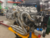
Engine as delivered. Note that the OEM-sized Super Damper is already fairly close to the water pulley

At my power level, the only way to achieve zero slip would be to use a cogged belt. You know, like the one in Mad Max. The issue is that they’re hard on a supercharger’s gears and they make a lot of noise which in a SL-C is about six inches from the driver’s ear. No problem, I’ll just fabricate a system that engages the supercharger with the flick of a switch. Apparently the movie achieved the trick with creative video editing and it’s not practical to build such a thing for anything other than a Mad Max tribute car.

The engine was delivered with a Daily Engineering dry sump oil system which included an ATI Super Damper with OEM dimensions (7.325” diameter and 8-ribs). To achieve 16 psi of boost the supercharger needs to spin at 21,000 RPMs which means that I had to significantly reduce the diameter of the stock Harrop supercharger pulley. The engine did over 1,000 HP on the dyno, but the belt began slipping at around 800 HP. That was on pump gas so when running on E85 the engine will attempt to transmit an additional 300ish HP after the belt starts slipping. Gotta fix that.

1626221683990.png

OEM-sized Super Damper (left) and custom Super Damper (right)

After taking some measurements I determined that I could fit a 10-rib Super Damper with 6% overdrive. I couldn’t use one of ATI’s larger-diameter units because the Daily dry sump requires a special ATI hub which isn’t even listed on their website and only a few shell assemblies are compatible with it. I spoke with several companies that could machine a larger pulley, but ATI has the best crank damper technology. To eliminate torsional crankshaft vibrations they attach a steel inertia weight to durometer elastomer rings retained via grooves CNC’d into the shell assembly.

I then learned that ATI will machine custom shell assemblies however they have a minimum 120-day lead time. The clock starts after you approve a dimensioned drawing produced by their engineering team. Since I had already replaced the mechanical water pump with a remote electric one and I was in the process of completely redesigning the supercharger and accessory serpentine belt systems the question became:
“What’s the biggest, baddest Super Damper that I can fit?”
I considered going with an obscene diameter, but that would have negatively impacted the design of the accessory brackets so I settled on 10-ribs and a 9.7” diameter.

That’s a 25% increase in width (i.e., number of ribs) and a 32% increase in diameter which increases the surface area between the supercharger pully and the belt by 58%. In addition, I previously posted about my custom GripTec supercharger pulley and my aftermarket tensioner. Combined, all of these changes combined will significantly reduce belt slip.

1626221750250.png

Two ribs projecting past the front face of the Super Damper where the accessory pulley mounts

ATI’s 10-rib Super Dampers aren’t designed to have a pulley mounted to their front face which presents two challenges. The first was that the holes on the bolt circle aren’t large enough to accommodate a pulley. Since it was a custom order, ATI took care of that for me. The bigger issue was that outermost two ribs project beyond the face of the Super Damper. While this reduces weight it causes the accessory belt to hit the Super Damper.

One way to resolve this would be to machine a spacer, but given that the pulley requires a boss that indexes the Super Damper’s ID, the right way to do it was to machine another custom pulley. So that’s what I did.

1626221834804.png

Custom accessory pullies; version one (left) and version two (right); my finger is pointing to the feature that compensates for the ribs that project past the front face of the Super Damper

1626221857984.png


The next step is to get a 10-rib Gates FleetRunner Micro-V belt (i.e., the green heavy duty ones) to fit. This will involve tweaking the location of the idler pulley and the rotational orientation of the tensioner.
 
Last edited:

Randy V

Moderator-Admin
Staff member
Admin
Lifetime Supporter
Does your engine have a keyed damper and crankshaft? I know in some cases a single 1/4” keyway is not strong enough so another is machined 180° off the first. I suppose it’s all relative to the amount of boost and backforce being produced. I do recall a number of early LS racing engines losing their balancers even though they were NA engines.
My most recent experience with running a wheezer was with an old school big block chevy and it was fine with a single tool-steel key.
3761EB9C-7CF7-463C-811B-9D0EC0AFFA7B.jpeg
 

Scott

Lifetime Supporter
Randy, that's a good question. I have a single keyway in the hub and crankshaft which my engine builder thinks is fine. I've been thinking about adding a dowel as well. ATI offers a pinning kit which includes two dowels and they will machine another keyway into my existing hub for something like $36. While their drilling jig ensures that the dowels are 180 degrees apart, it doesn't provide a way to index the key so there's no way ensure that the everything is aligned.

The ATI jig places the dowels around the the sides of the crank and Abe has used kits that place the dowels in the end of the frank. However, I'm not sure how I would ensure that the holes were aligned with the keyway - or maybe the hub and crank are drilled in place so alignment isn't an issue. If anyone has any suggestions, I'd love to hear them.

https://www.jegs.com/i/ICT-Billet/335/551917/10002/-1

https://shop.brutespeed.com/ATI-MD001I-003-250-OD-X-75-L-SS-Dowel-Pin-MD001I-003.htm

https://malexmotorsports.com/produc...s3-lsx-crankshaft-balancer-lsa-tool-drill-jig
 
Last edited:

Johan

Supporter
Scott, if you use the dowels in the end of the crank, the holes are drilled with the damper installed so alignment is not an issue.
 

Scott

Lifetime Supporter
Nothing happened with the car during the last couple of weeks because I was in Portugal. Now that I’m back the right primaries are welded. Once they’re tacked in place, the engine will come out again, a welding jig will be fabricated and the primaries will be finish welded to the flanges.

1628645509484.png


1628645524074.png


1628645546875.png
 

Attachments

  • 1628645523280.png
    1628645523280.png
    3.4 MB · Views: 142
Nothing happened with the car during the last couple of weeks because I was in Portugal. Now that I’m back the right primaries are welded. Once they’re tacked in place, the engine will come out again, a welding jig will be fabricated and the primaries will be finish welded to the flanges.

Great work!! I know you toyed with the idea of 8 into 1 headers first and transitioned to crossover. I've been considering making an 8 into 1 header as well but lately considering trying to fit the GTM kook headers and maybe joining the collectors. I almost can't even buy the stainless material at the cost of the kooks not to mention the time. I know you're not done yet, but would you say it was worth the effort?
 

Scott

Lifetime Supporter
would you say it was worth the effort?

IMO the only things worth doing are hard. And sometimes they're also expensive LOL in any event so long as I don't have any heat issues, it's more than worth it.

The right primaries were tacked to the flanges and the engine was pulled. This is the first time that I’ve seen it all put together and I think that it looks pretty bad ass. The next step is to fabricate the welding jig for the right header, finish welding the right header flanges and weld v-band clamps to the merge collectors.

This also gave me an opportunity to bolt up my latest revision of the serpentine brackets, spacers, pulleys and belts. I need to make a few tweaks, but I was able to get a Gates 10-rib MICRO-V FleetRunner (aka green belt) to fit.

1628899540067.png


1628899571532.png


1628899601607.png


1628899631169.png


1628899663772.png


1628899710183.png


1628899755460.png


1628899798595.png
 

Attachments

  • 1628899709853.png
    1628899709853.png
    1.7 MB · Views: 138

Scott

Lifetime Supporter
The pneumatic shift servo is powered by a Shiftec Air Power Source (APS) which has a max operating pressure of 9.8 bar (142 psi). The servo’s ram connects to the shift lever via a 1/4”-28 rod end. I wanted a high-quality bolt without any threads in shear so I purchased an AN bolt with a 0.688” grip from Pegasus Auto Racing. The advantages of AN bolts are that the grip lengths are available in 1/8” increments, they are less brittle than SAE bolts and, so long as you don’t purchase a counterfeit, they are manufactured to a high standard, which is why you purchase them from a place like Pegasus, Aircraft Spruce, McMaster, etc. The shift lever’s clevis was too tight to accommodate misalignment washers so I used two thin (0.032”) AN washers.

The servo’s other side is an M8 rod end. I used two misalignment washers and an aluminum spacer that I machined on the lathe and to ensure that the shift servo was orthogonal to the shift arm. I then fabricated a bracket out of 1/4” 6061 aluminum to place the shift servo’s mounting bolt in double shear. It required an offset bend which is a little tricky to get perfect.

1629249463612.png

Bend lines scribed in layout dye on the edge and marked in pen on the actual bend location. The distance between the bend lines is 4.407”. Note the 1/8” aluminum scraps taped in place to prevent the upper die from damaging the material.

I measured how far the outer misalignment washer was from the transaxle, decided that I wanted the bend lines to be one inch from the center of the mounting holes which allowed me to determine the length of the base of the triangle. I then used the Pythagorean theorem to figure out the distance between the bend lines (i.e., the hypotenuse) and the sine function to figure out the bend angle. My middle school math teacher would be happy to know that the SOH CAH TOA mnemonic stuck and I didn’t need to Google it — well actually I did just to make sure, but I had it right.

shift_servo_2.jpg


I purchased an Eastwood press brake attachment that fits my 20-ton Harbor Freight hydraulic press. The advantage over the garage-made dies that I used in a previous post is that the top and bottom dies are automatically aligned and the unit is heavy which makes it easy to use a square to align the material being bent. The downside is that the upper die is pointed rather than a piece of 3/4” round bar which gouges 1/4” aluminum.

I had calculated the bend angle to be 16.2 degrees so I used a digital angle gauge to achieve 9.2 degrees. Since both sides are being equally bent and the gauge only measures one side I divided the number by two and then added one degree for spring back. While the trig is exact it doesn’t take into account the bend radius and that the material stretches when bent. After experimenting with a few pieces I determined that the target angle should be 10 degrees and that a piece of 1/8” of scrap aluminum placed on top prevented the upper die from leaving a crease in the part.

I found that leaving the ends long allowed me to easily determine if they were parallel. Once the piece was bent I used a belt sander to remove the deformation on the sides caused by the bending process. Not doing so will result in the vice jaws only squeezing on bulges which will throw off digital readout (DRO) measurements. Worst the bulges aren’t equal which means that the largest set will act as a pivot point which can cause the part to spring upwards and out of the vice when being machined. This not not only wrecks the part, but it can create a dangerous situation. I had that happen with a previous part and I know better now.

1629249565053.png

Transfer screws; the handle stores the screws and is used to thread them the desired distance into the hole (i.e., so that the pointed tip barely protrudes from the hole)

I then drilled an M8 hole in the bracket and mounted the servo. The next challenge was to precisely determine where the the second mounting hole should be drilled. This would be difficult to achieve by measuring. Instead, I applied layout dye to the back of the bracket and used a transfer screw to scribe a short ark. The intersection of that ark and the midpoint of bracket was the exact location of the hole. The result was pretty much zero slop even before the screws are tightened.

The next step was to lighten the bracket with holes, slots and rounded ends.

shift_servo_4.jpg

All of the parts. The bracket and spacer are custom.


1629249625377.png

Shift servo and bracket mounted to bosses on the transaxle

1629249648670.png

The offset bend is apparent in this picture

The next step is to figure out how to route the wires and the air supply hose.
 
Does this system monitor current gear selection and vehicle speed to prevent an inadvertent engine over-rev situation with downshifting?
 

Scott

Lifetime Supporter
David,

No and yes... The shift servo is a simple device that is controlled via CAN bus. So it only does what it's told, including something stupid. However, I have a MoTeC ECU that will implement engine management, traction control, gear shift strategy etc. It will monitor RPM, the gear position sensor that comes with the transaxle, paddle shifter input, etc. The gear shift strategy will require configuration/programming to prevent overrevving during a downshift, accidently putting the car into reverse while slamming through downshifts, etc. That's simple to do. However, just like an engine, it will require a fair amount of tuning to get everything working smoothly; air supply pressure, severity and duration of torque cut, duration and severity of torque resumption etc. I'll have two driver-selectable tunes; one for the street and the track.
 
Back
Top