S2's Build Thread

Scott

Lifetime Supporter
1629926184460.png


1629926211847.png


1629926233850.png


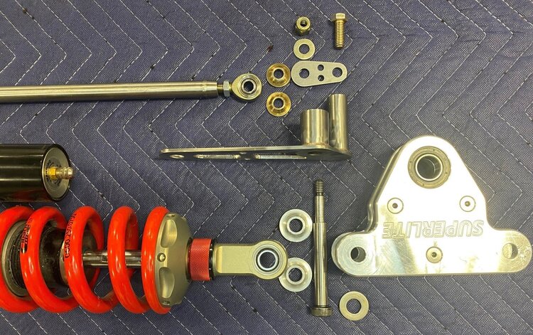
In previous posts I evaluated and selected a tensioner, I had a custom GripTec supercharger pulley machined and I had a massive 9.7” Superdamper machined. Today I finally completed the rest of supercharger’s serpentine system. It was a lot of work. There are no OEM parts, most of the aftermarket parts are custom and I designed and fabricated everything else.

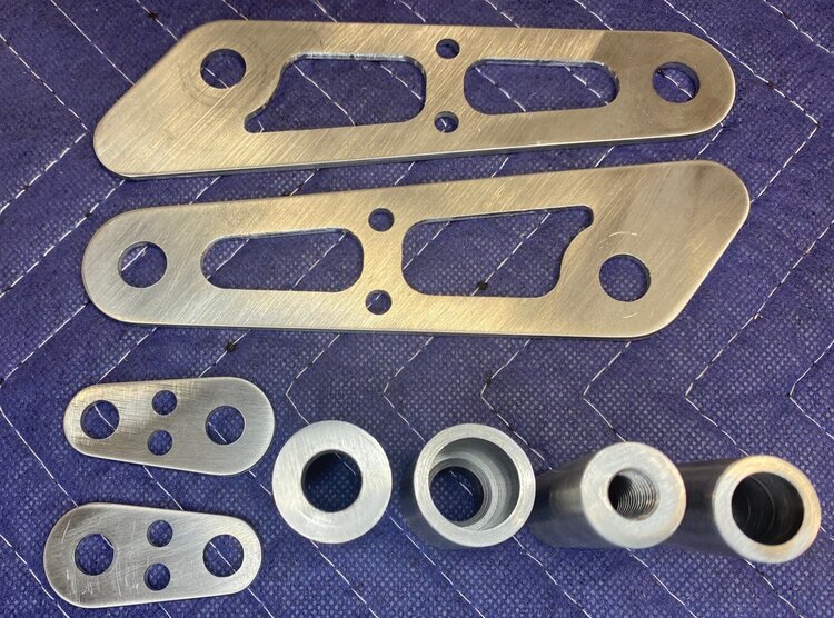
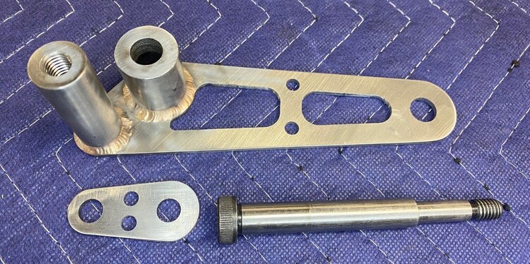
The large plates were laser-cut from 1/4” 304 stainless steel (prior pictures were of the mild-steel prototypes). I used a horizontal belt sander to clean up the outer edges and a Dremel loaded with a small sanding drum for the circular cutouts and a few of the tight radiuses that the belt sander couldn’t reach. To break the edges I used a deburring tool on the interior features and a deburring wheel on the exterior. The result isn’t as nice as as CNC’d pieces, but it’s close at a fraction of the price.

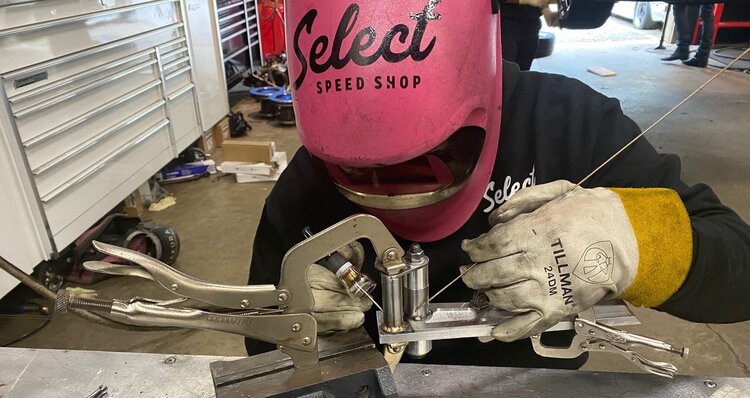
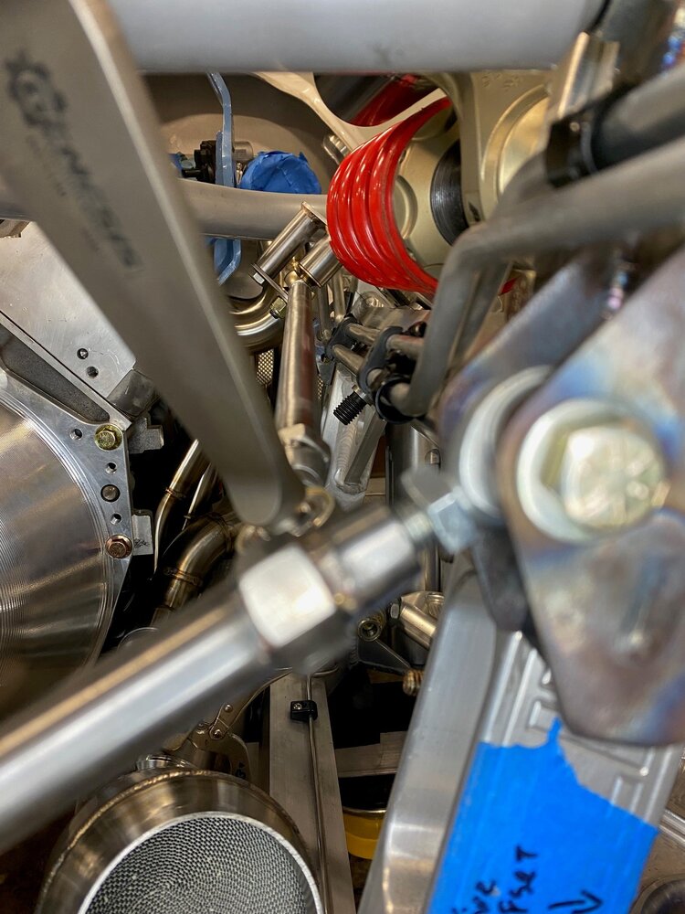
Since the cylinders are staggered the right head (left side of picture) sits behind the plane of the block and the left head. I machined four aluminum spacers to sit between the head and the rear plate, but it was unwieldy to hold them in place when installing the brackets so I had Abe weld them to a frame.

1629926273014.png

The right head (left side of the picture) sits behind the front of the block and left head

1629926402828.png

Spring/Roll/Tension/Split/Expansion Pin

The shape of the spacer for the tensioner wouldn’t of been trivial to mill and the holes needed to be precise so I decided to have it laser cut. However, the spacer was thicker than the laser could handle so I cut two pieces and milled one of them to meet the target thickness. I then used two spring pins (aka roll, tension, split, or expansion pins) to prevent them from moving in relation to one another. Spring pins have a slot in them and when they are hammered into an undersized hole they spring outwards and apply tension. I have used them in steel parts before, but I found that they gouged the side of the aluminum holes and pushed material into the hole. To address, I tried to compress the beveled end with pliers which resulted in the pin being shot across the room. I found that a vice allowed me to get the perfect amount of compression without the launching problem. This allowed me to pound the pins in. They would be a bitch to remove which is exactly what I wanted for this application because they will never be removed. The final step was to clean up the edges on a belt sander. If you look carefully at the picture below, you’ll see line separating the top and bottom pieces.

1629926443391.png

Two-piece spacer for the tensioner; top piece was machined to target thickness; both are pinned together

All of the other spacers were machined from 6061 rod on the lathe. Most were simple cylinders, but several required tight-tolerance shoulders to index the ID of the pulley bearings.

1629926466142.png

Two spacers and one cover with shoulders that index the ID of a pulley bearing

As mentioned in a previous post, I was able to get a Gates 10-rib MICRO-V FleetRunner (aka green belt) to fit. They have superior construction and are, to my knowledge, the best serpentine belts for supercharged applications. Beyond having superior construction, it is several inches shorter and 25% wider (i.e., 8 vs. 6 ribs) than the one provided by Harrop. Since elongation is proportional to length and inversely proportional to width, the belt will stretch less on first principals.

1629926500747.png


1629926531939.png


1629926561525.png
 

Scott

Lifetime Supporter
The Albins ST6-M automatically locks the reverse gear out. To put it into reverse the driver must pull a cable to disengage the lock and only then downshift. This makes a lot of sense because it’s a sequential transaxle and you don’t want the driver to accidently put the car into reverse when slamming through downshifts — seems like something that I would do.

1630358719216.png

Cable bracket in foreground, lock shaft without the cap to the right

Since I’m using paddle shifters and a pneumatic shift servo I don’t want to clutter the cockpit with another lever/handle and I really don’t want to run a mechanical cable to the rear of the car. Instead, I will program the MoTeC ECU to monitor the gear position sensor and to ignore downshift commands if the car is in neutral (i.e., reverse is next) and moving. I’ll probably also require the driver to depress a button on the steering wheel to enable reverse as an additional safety measure. So rather than a mechanical lockout, I’ll have a logical one.

1630358748023.png

From left to right; Cable bracket, lock shaft cap and lock mechanism

A spring keeps the lock engaged and to disengage the wire pulls the lock’s shaft outwards. The wire is attached to a cap which utilizes a set screw to engage a groove in the end of the lock’s shaft. To keep the lock disengaged I machined a spacer on the lathe to replace the cap. It uses two set screws to engage the groove in the lock’s shaft and keep it pulled away from the transaxle.

1630358776746.png

Custom spacer (fore) and lock mechanism (rear)

I was thrilled, I machined exactly what I wanted the first time which doesn’t happen all that often. The last step was to install it by pulling the shaft out, holding it in place with non-marring needle nose pliers while sliding the spacer over the shaft and tightening the first set screw. The challenge was that there was very little room between the spacer and the transaxle to grip the shaft. This resulted in lots of profanity and no success.
Frustrated with that approach I wondered if I could remove the lock mechanism, compress the spring on the bench and install the spacer. How much damage could removing two socket head cap screws cause? In this case none. I pulled the mechanism out, compress the spring and installed the spacer. I then began wondering if I could just replace everything with a cover plate so I called Weddle“yep, no problem removing it so long as you have an electronic lock out.”

Do’h! I made a beautiful part to solve the wrong problem, so into the recycle pile it went. I designed a cover plate, 3D-printed a prototype and laser cut a final part from 1/8” 304 stainless steel. Problem solved!

1630358833846.png

3D-printed prototype (left) and final stainless steel part (right), the hole in the middle of the prototype was to reduce material and print time
 
Do you have access to a laser cutter, or do you use a service? I’m looking for an online service so it would be great if you had a recommendation.

I also have been 3D printing mine to ensure they are ready to cut.
 

Scott

Lifetime Supporter
Alan, I highly recommend SendCutSend.com. They have outstanding prices, online quoting/ordering, lots of of material choice, typically a one-week turn around. Their quantity one pricing is lower than my local company's quantity 50 pricing and they're 2-3x faster because the local guys aren't focused on Mickey Mouse orders. Most materials have a $29 minimum per which incudes 2-day FedEx. These were $1.42 each so I ordered 20 which added up to $28.40 and the system rounded up to the $29 minimum. If I had something else to cut out of 1/8" stainless I would have added that and less cover plates.
 

Scott

Lifetime Supporter
I should have mentioned that if the parts meet a certain size criteria they deburr both sides which usually removes all of the mill scale. Below is a picture of my first order. It's mostly 1/8" 4130 with a few piece of 1/4" 6061. Most of the pieces were deburred. The orders are shrink wrapped which surprised me. It keeps the aluminum from getting scratched and steel from flash rusting if you don't use it right away.

1630425946939.jpeg
 

Scott

Lifetime Supporter
I installed the flywheel today. I have an LS7 so I ordered an LS flywheel locating dowel and when I went to install it I realized that it was way too small. WTF? I have a built motor and it has a Callies DragonSlayer billet crankshaft with an LT, rather than an LS, bolt pattern. D’OH! Fortunately, I had ordered the flywheel with the correct pattern.

The LT is clearly designed to deliver more torque, it has an extra bolt and the flywheel locating dowel is significantly larger. The LS dowel pictured below is a GM Performance part and it looks like something from the Home Depot bargain bin.

1630635343595.png

Flywheel locating dowels; LT on left and LS on right

I tapped the dowel in with a brass hammer and noticed that it wasn’t centered between two holes. This meant that the flange on one of the swanky12-point flanged bolts wouldn’t clear the dowel. The solution was to chuck it up in the lathe and take 0.050” off of the flange’s OD.

1630635389319.png

Note that the dowel is closer to the bolt on the left whose flange has already been machined

1630635413624.png

50 thousands has been machined off of the left bolt’s flange
 
Scott, I was looking at your remote pump setup and noticed you were not using a crossover tube on the block and instead used individual fittings for hose. Any particular reason? Preference or wouldn't fit behind the belt setup?
 

Scott

Lifetime Supporter
Jeff,

I didn't find a solution that I liked. I considered fabricating a manifold, but here's why I went with separate hoses:
  • It's easier to route two smaller hoses than one large one
  • Swivel fittings make it easy to tweak orientation (i.e., things change!)
  • I was able to use Wiggins clam-shell couplings... once you use those you never want to go back
  • It allowed me to implement a swirl pot to deaerate the coolant
  • Less weight
I fabricated a custom inlet and outlet manifold and had it welded to the cap of the water pump. I also fabricated a custom coolant swirl pot. This allowed me to route everything exactly as I wanted without having adapters etc. all over the place.

1631207158813.jpeg

Swirl pot on left. Two tangential inlets on top and one tangential outlet on bottom. The outlet clamshell connects directly to the stainless steel tube that runs down the left side pod. Air vent at top and drain on the bottom.

Pierburg water pump with custom manifold on right. The inlet, from top to bottom, is the heater return, the expansion tank / fill and the return from the radiator. The outlets go to the heads.
 

Scott

Lifetime Supporter
I finally got around to installing the triple-carbon clutch that I discussed in a previous post. The first step was to install the pilot bearing in the crankshaft. I applied a little anti-seize on the sides and used a 32 mm socket, a short socket extension and a hammer to tap it into the crankshaft. Easy peasy.

To remove any burrs or imperfections from both the clutch hub and the input spline I applied the provided lapping compound to the input spline and I individually slid each of the three disks back and forth on the spline. This was easy to do, but it was a pain in the ass to remove all of the lapping compound from the spline’s valleys. With that done, it was straight forward to align the clutch and mount it to the flywheel.

1631401962770.png

Clutch is installed

1631401978829.png

Stock bearing (left) and new bearing with custom spacer (right)

Agile Automotive and RPS collaborated to create a complete solution. They provided a larger throwout bearing and a custom spacer to set the correct distance between the throwout bearing and the pressure plate fingers. I used a bearing separator to remove the stock bearing and a hydraulic press to mount the spacer to the new bearing. While using a hydraulic press to push the bearing/spacer assembly onto the slave cylinder I damaged the slave cylinder’s piston. DO’H!

1631402003364.png


Fortunately Weddle stocks just the piston so I had them FedEx me one. When it arrived I noticed that it was longer than the one that I had, so they FedEx’d a second one and it had the same problem. After some measuring and a lot of discussion, we determined that Albins had installed the wrong piston at the factory! The total height of the piston should be 49.5 mm rather than 58 mm.

The extra length results in a longer shoulder which was a contributing factor to the damage inflicted on the original piston. Had I not damaged it the extra length would have gone unnoticed because there are no part numbers on the pistons and no measurements are provided in the manual. The longer piston would have likely destroyed the $5,000 clutch, requiring me to pull the whole tail of the car apart to replace it!

1631402026727.png

Slave cylinder removed

Once that cluster was sorted out it was an easy matter to reinstall the slave cylinder. I had used a long hex bit socket to remove it, but the wider throwout bearing necessitates a ball end version. The clutch pressure and bleed fittings have tapered threads. The manual didn’t specify a compound so I used Gasolia liquid thread sealant.

1631402051568.png

Slave cylinder with upgraded throwout bearing and spacer installed. The top left yellow-zinc-plated fitting is the clutch bleed and the one below it is the clutch pressure inlet.

The spline isn’t tapered at the tip which makes it more challenging to align it with the clutch hub and you need to be careful to not crack the carbon disks. As can be seen below, the engine was bolted to a hydraulic lift table and a motorcycle scissor jack was placed under the billet oil pan. The transaxle was suspended from an engine hoist via an engine load leveler. This allowed me to get everything lined up without any help and without needing to shake the hell out of the transaxle.

1631402074927.png


While I was waiting for the parts to arrive, I noticed that one of the socket head cap screws had developed some surface rust — gasp. The studs and 12-point nuts have a nice coating, but all of the socket head cap screws are black oxide. Albins, you couldn’t spring for a extra couple of dollars? So I replaced all 62 socket head cap screws with zinc-plated screws which was irritating because I needed to buy six different types of screws each with a 50 or 100-count box.
 
Last edited:

Scott

Lifetime Supporter
I mounted the rear sway bar in a previous post and the next step was to attach it to the bellcranks. The adjustable sway bar blade accepts a 3/8” rod end. However, the other side of rear sway bar link is attached to the same 1/2” bolt that affixes the shock absorber to the bellcrank. While it would be easy to fabricate a link with a 3/8” rod end on one side and a 1/2” rod end on the other side, that would be overkill. 1/8” might not seem like a big difference, but a 1/2” rod end dwarfs a 3/8” one.

rsb2.jpg

1/2” rod end (left) and 3/8” rod end (right)

It also requires a larger tube-end weld nut, jam nut and tube which adds weight and bulk making it more difficult to clear the shock absorber spring. I spent a couple of nights scouring the Internet for a unicorn — a rod end with a 1/2” bore and a 3/8” male thread. If it exists, I couldn’t find it.

I considered machining a 3/8” shoulder and a 3/8” thread on the tip of a 1/2” Grade 8 screw, but I’m not comfortable machining threads yet. I then realized that a shoulder screw would be a better starting point. They are comparable in strength to a Grade 8 screw and McMaster offers 1/2” shoulder screws with a 3/8”-16 thread with grip lengths in 1/4” increments. I purchased two with a 4” grip which was long enough to allow the link to clear the shock absorber. All I needed to do was turn 1/8” off of the last 1” of the grip in the lathe.
That should be easy, right? Nope! No matter what I tried I couldn’t get a good finish. I had purchased an indexable carbide tool set because I didn’t want to learn how to grind High-Speed Steel (HSS) tools. Apparently, carbide likes much higher speed and feed rates than my lathe can do (think CNC). It worked fine on aluminum, but it wasn’t working on this grade of steel. After doing a little research, I discovered Arthur R. Warner Co. who offers indexable HSS inserts. I purchased one of their tool sets and they provided an excellent finish.
Shoulder screws are more difficult than normal screws to install through suspension parts because the shoulder has a 90-degree edge that gets hung up on anything that isn’t perfectly aligned (e.g., safety washers, rod end’s mono ball, etc.). To mitigate this issue I chamfered the 90-degree edge.

rsb1.jpg

Stock shoulder screw (top) and modified shoulder screw (bottom)

The next step was to design and fabricate a bracket to position the link 1.3”from the bellcrank and to put the shoulder screw in double shear.
I laser cut a plate from 1/8” 4130 that attaches to the underside of the bellcrank via the existing 1/2” bolt holes. Using the lathe, I machined a spacer to fit between the bellcrank and the misalignment washer. It’s critical that the misalignment washer binds on the bellcrank (via the spacer) and not the face of the shoulder screw. I used 1”4130 rod to match the OD of the misalignment washer and drilled a 1/2” through hole. To reduce the weight of the piece I machined the all but the last 0.4” of the ID to 3/4”. The lathe would have been ideal for this, but my Jacob’s chuck maxes out at 1/2”.
Instead, I mounted a three-jaw chuck to the mill and used a 3/4” 4-flute end mill. Given the hard alloy steel and cheap end mill I was worried about chatter, but using the online speed/feed calculator (460 RPM) and the quill (as opposed to the z-axis handle) allowed me to cut it like butter. I assume that this was due to the 1/2” hole already being drilled. I had to stop the mill several times to remove the swarf which is as sharp as shit… yeah, I managed to cut my finger which wasn’t a big deal because the mill was off. I had become comfortable dealing with aluminum and this was one of those important lessons which could have been much worst. After employing a Band-Aide, I used a 3/4” countersink to chamfer the spacer’s internal face to make it easier to feed the shoulder screw through it.

rsb8.jpg

1” 4130 rod, 3/4” 4-flute end mill and sharp-as-shit swarf

rsb9.jpg

4 laser cut parts; base plates and double-shear plates. 4 machined parts; from left to right, spacer (top view), spacer (bottom view), post (top view), and post (bottom view)

I machined a post to support the double shear plate from 3/4” 4130 rod. One end was drilled and tapped for 3/8”-16 and, similar to the spacer, the other end was machined with a 1/2” end mill to reduce weight.

Because all of the welding was going to be done at one end, I fabricated a simple welding jig from consisting of a plate and two spacers. I used aluminum because it’s an excellent heat sink. ER70S rod to add some large tacks that were structurally strong enough, but minimized the chances of warping. I wanted the full circumference welded so he used silicon bronze rod because we didn’t need the strength and it requires half as much current which equates to a lot less heat.

rsb20.jpg

Abe welding on the jig

rsb23.jpg

The custom parts; bellcrank bracket, double shear plate and modified shoulder screw

rsb21.jpg

Exploded part view

The links were fabricated from 4130 tube, 4130 tube-end weld nuts and stainless steel hex nuts. The aluminum tubes located between the sway bar link and chassis are for the front and right-rear air jacks.

rsb33.jpg


rsb29.jpg


rsb31.jpg

The adjustable blade extends down from the top left corner

The next step is to run the control cable.
 
Scott I'm in process of replacing my rear springs. The 650 lb springs are too light for spirited driving on the poorly maintained Pennsylvania roads. I recently got a set of Hyperco 850lb springs but their outside diameter is too large and they interfere with the frame. I was checking into a set of QA1 850lb springs when I became aware that Eibach makes an 800 lb spring (Which I think would be a better weight) . I see you are using Eibachs and they look to have more clearance than the Qa1s I currently have. Long story short what weight are your rear springs? And if you could measure their diameter I would greatly appreciate it. Thanks Rich
 

Scott

Lifetime Supporter
Rich,

Thanks for the compliment. The rear springs are Eibach 0600.250.0750 (link here EIBACH COILOVER SPRING). They are 750 lbs/in and have an OD of about 1.6" which provides plenty of clearance.
 
Back
Top