Howard Jones
Supporter
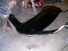
Oh...oh........that looks a little too good...Rob. You've really screwed em up now!!! See guys, this is what happens when you sit in the garage, drink a beer, and ponder the car for a couple of hours with Rob.

")
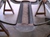
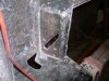
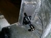
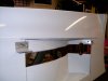
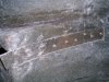
Oh! OKay! Now I understand! Thanks!The area beside the rectangular box is occupied by the roll cage bars, making the opening elliptical would only make the job more complicated with little benefit.

Howard:
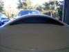
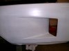
If you're letting more air into the engine compartment, don't you need to make accommodations for that air to get out? Otherwise, wouldn't you end up with a high pressure area within the engine compartment?
Just saying...