
- Forums
- GT40 Replica Manufacturers' Corner
- RCR Forum - RCR40/SLC/917/Superlite Aero
- The SLC Clubhouse
You are using an out of date browser. It may not display this or other websites correctly.
You should upgrade or use an alternative browser.
You should upgrade or use an alternative browser.
SLC 24 Howard Jones
- Thread starter Howard Jones
- Start date
Cam how many do you need?
Nice. I've been looking for 1.5" insulated clamps. I couldn't find them at Aircraft Spruce. do you know what they called them?
Also where are you getting you 1.5" blue Silicone couplings?
This is who supplies us: Wesco Aircraft Hardware - Fastening the Aerospace World with all of our hardware..
Howard Jones
Supporter
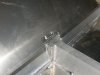
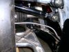
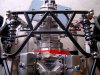
This is how I finally did my rear anti-roll bar. There isn't a straight forward way to do this. First there isn't much room to work with and second there isn't anything to bolt onto as far as the A-arms go. Also everything back there is at different angles so it is hard to work with the small amount of rod end defection angle and not bind them up as the suspension moves. It took me awhile and several tin mock-ups to come up with the locations and angles that will work and be simple. If the upper A-arms had been parallel to the torsion arms it would be easy but they are at odd angles to each other and it took a little thinking to come up with this. If I had bent them to be parallel to the A-arms then the Rod ends would bind up.
After talking to Fran I decided to drill and tap a hole into the upper A-arm, make a bracket and run a link down to the torsion arm. Fran sent me a second set of upper A-arms and the rod ends and hardware. I already had the torsion arms and the bar itself was mounted on the chassis when the car originally arrived.
The torsion arms were a bit too long and straight so I cut them off and bent them with torch, a big F'in vice and a 8 foot long breaker bar along with a really big friend at work.
I made the upper bracket's and welded together the bungs and tubing for the links.
The torsion arms have 5 holes in them for adjustment so when I get it on the track I can see how it tunes up.
Attachments
Howard Jones
Supporter
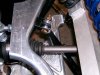
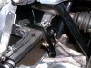
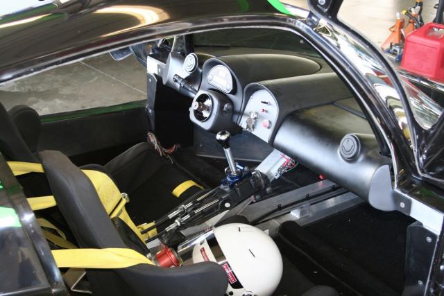
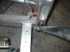
My basic plan has been to mount things that must be in place before moving on so that subsequently other components do not turn out to be in the way or need to occupy the same space.
This is sometimes difficult on a first build and without other finished examples to look at.
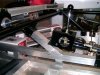
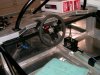
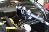
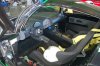
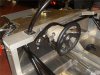
Here we have an issue with where I need to mount the shifter. At you can see a chassis square tube is in the way.
A while back I bought a tig welder and I have been practicing on the bench. I pretty much have steel down but until the last few day I wasn't comfortable enough with alum to attempt welding on my nice new chassis.
But sooner or later Ya just gotta go for it. It didn't come out half bad. Not as pretty as Frans guys but done as correctly as I know how. Here's the results.
The first picture illustrates the problem and the others show you my solution. I have noted that later chassis numbers seam to have a different layout in this area and would not need to be modified like this.
Now I can mount a seat and the peddle box and move on with the rest of the interior.
This is sometimes difficult on a first build and without other finished examples to look at.
Here we have an issue with where I need to mount the shifter. At you can see a chassis square tube is in the way.
A while back I bought a tig welder and I have been practicing on the bench. I pretty much have steel down but until the last few day I wasn't comfortable enough with alum to attempt welding on my nice new chassis.
But sooner or later Ya just gotta go for it. It didn't come out half bad. Not as pretty as Frans guys but done as correctly as I know how. Here's the results.
The first picture illustrates the problem and the others show you my solution. I have noted that later chassis numbers seam to have a different layout in this area and would not need to be modified like this.
Now I can mount a seat and the peddle box and move on with the rest of the interior.
Attachments
Some pics of other cars for reference.
Frans car: different shifter with and without center console

Aussie: Old style chassis with new shifter
Aussie: New style chassis

Looks like Howard is Bang-On! Besides, I don't even know if he is going to use a dash and I'm pretty sure there will not be a center console in his car. Please clarify Howard.
Frans car: different shifter with and without center console
Aussie: Old style chassis with new shifter
Aussie: New style chassis
Looks like Howard is Bang-On! Besides, I don't even know if he is going to use a dash and I'm pretty sure there will not be a center console in his car. Please clarify Howard.
Attachments

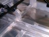
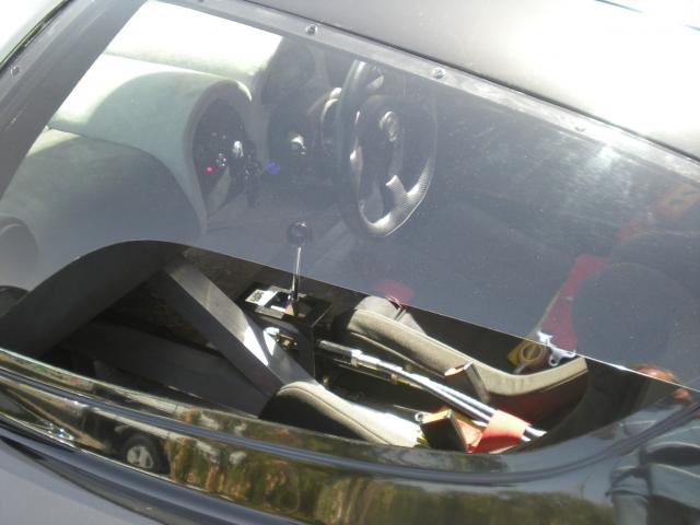
Two days ago, I made my bracket for the Brantwood cable shifter. Much like Howards but attached to the angled tube, not flush with it. Offset to passenger side slightly.
I put a 1-1/4" 90 degree bend at the back end to allow clearance for the cable adjusters. Used 3/16 aluminum plate x 3" wide for this.
It winds up with plenty of dash clearance and the shift knob is about 4" from the steering wheel. Howard will have sufficient dash clearance too.
I put a 1-1/4" 90 degree bend at the back end to allow clearance for the cable adjusters. Used 3/16 aluminum plate x 3" wide for this.
It winds up with plenty of dash clearance and the shift knob is about 4" from the steering wheel. Howard will have sufficient dash clearance too.
Howard Jones
Supporter
I won't be using the dash, although I do have it. My intention is to build a alum pannel "dash" much like most current race cars. I also have a roll cage tube that runs across the chassis below the steering wheel. What you see in the pictures is what will be in the car when it is done. My intention here is to mount the shifter as it was intended to be mounted.
This is going to be a full on track car. No carpet, panneling, and a single seat to begin with.
The only street car concessions are what I won't do that would ruin it for that purpose shuold I want to convert it for street use later such as a full on NASCAR style cage inside the car.
I do want to add a second seat later after I have it sorted out so I can haul a ride along.
This car should be perfect for a two place track car with it's nice roomy interior.
Howard,
Great job on the shift location! It looks as if I'll have to do the same.
Fran changed the full cage somewhat so that the front and side bars won't interfere with the seats/door panels/dash. Note that my dash bar travels over the steering column, etc.
Sent my fuel can off to be a template for a fuel cell today. The Jesel roller rockers are finally being shipped to me as well. So, a little progress....
Attachments
Howard Jones
Supporter
Doc, keep me up to date with your fuel cell progress if you would, thanks, Howard.
Howard,
Great job on the shift location! It looks as if I'll have to do the same.
Fran changed the full cage somewhat so that the front and side bars won't interfere with the seats/door panels/dash. Note that my dash bar travels over the steering column, etc.
Sent my fuel can off to be a template for a fuel cell today. The Jesel roller rockers are finally being shipped to me as well. So, a little progress....
So DOC do you have to make your own fuel cells with the SLC?
Craig Gillingham
Banned because I can't follow the forum rules.
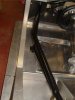
Hi,
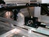
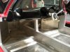
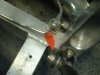
I am sure RCR have given you information on the early incorrect rocker arm mounting points that needs addressing as they potentially could pop through as the geometry angle is wrong.
I have just seen your picture.
In this picture: when mounting (or moving) to the correct point marked "X.......on testing my chassis cracked in the area marked "circle"
I informed fran months ago and his email was "it must have been an incorrect welding schedule on my chassis"
we have done a chassis mod on the aspira.
just wondering if any other cars that have the new mounting point at the top of the aluminium upright - that have done extensive testing -
have also experienced this problem?
or again maybe i am the unlucky one...")
regards
I am sure RCR have given you information on the early incorrect rocker arm mounting points that needs addressing as they potentially could pop through as the geometry angle is wrong.
I have just seen your picture.
In this picture: when mounting (or moving) to the correct point marked "X.......on testing my chassis cracked in the area marked "circle"
I informed fran months ago and his email was "it must have been an incorrect welding schedule on my chassis"
we have done a chassis mod on the aspira.
just wondering if any other cars that have the new mounting point at the top of the aluminium upright - that have done extensive testing -
have also experienced this problem?
or again maybe i am the unlucky one...
regards
Attachments
Craig Gillingham
Banned because I can't follow the forum rules.
Similar threads
- Replies
- 14
- Views
- 2K
- Replies
- 5
- Views
- 2K