
- Forums
- GT40 Replica Manufacturers' Corner
- RCR Forum - RCR40/SLC/917/Superlite Aero
- The SLC Clubhouse
You are using an out of date browser. It may not display this or other websites correctly.
You should upgrade or use an alternative browser.
You should upgrade or use an alternative browser.
SLC 24 Howard Jones
- Thread starter Howard Jones
- Start date
Howard Jones
Supporter
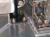
I was studying your pedal setup and wondering if you have enough room in the 3/4'' heather hoses to move the pedals around much? it looks like in the position they're, you can't bring it further anymore?
Also, have you given any thought as to how to run your throttle cable? I think we're the only 2 using a carb, and I've run out of ideas that don't involve going through the cockpit, heh
Also, have you given any thought as to how to run your throttle cable? I think we're the only 2 using a carb, and I've run out of ideas that don't involve going through the cockpit, heh
Howard Jones
Supporter
No heater in my car. I will use a push pull cable for the carb linkage and will run it the same way as the shifter push pull cables.
No heater in my car. I will use a push pull cable for the carb linkage and will run it the same way as the shifter push pull cables.
not heater; I was referring to the black heater hoses Wilwood gives you to attach to the top of the cylinders that goes to the remote mounted cylinders that holds the brake/clutch fluids- it looks like if you moved your pedal mount forward there isn't any slack in them to go more forward.
Howard Jones
Supporter
I cut them to fit with a little room to move the peddles. They can go back and forth about 2-3 inchs without replacing them. There is more slack in the forward radiator compartment. I made the peddles adjustable mainly to be able to fine tune their placement to suit me when I start tracking the car. There isn't any intention to provide adjustment for other drivers. 2-3 inchs will be more than enough. I think I am within a 1/2 inch of dead on, now.
There is however a lot of room in the footwells. I think that a 6' 4" plus guy could drive the car if the seat and peddles are located to suit. I am 5' 3" and I tend to place the seat forward and the peddles farther to the rear. The passenger seat, when I install one, will be located full rear posistion and bolted down for good.
There is however a lot of room in the footwells. I think that a 6' 4" plus guy could drive the car if the seat and peddles are located to suit. I am 5' 3" and I tend to place the seat forward and the peddles farther to the rear. The passenger seat, when I install one, will be located full rear posistion and bolted down for good.
Howard Jones
Supporter
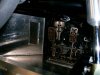
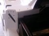
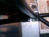
I have finally finished with bolting in the roll cage. Remember this is the prototype that Fran and I discussed while the car was still at his shop. The newer version is a little different and from what I have seen of it, it looks easier to install.
Anyway a little trimming of the body work to finish fit it at the front of the foot-box, drilling the holes for the cage flange mounts for the foot-well section and the roll cage is in for good. The only tuff thing to do was the top outboard corner flange bolt & nut for the foot box section tubing. Good thing I have little hands! I am however glad to be done working up inside the foot box, at least for now. Hard on the ol back.
The body really fits pretty well as it came. My car has the full cage in it and so the brake lines exit the foot well higher to clear the cage tubing. This required a little clearance half hole. No big deal.
Attachments
Last edited:
Howard Jones
Supporter
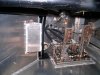
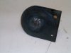
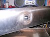
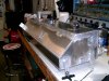
Update. I decided to use the fuel tank that came with the car. At least until a fuel-cell is available. The original tank in a big aluminum box with a inlet on the side and a bunch of assorted bungs welded on it in various places.
I patched all the bung holes after cutting off the bungs and cut down the top of the tank at the fill hole level. As you see it, it holds 14.5 gals of water. It is 9 1/2 " tall now and there is plenty of room on the top to blot on a fill plate, pick up, and fuel level sender.
Why change it you ask? The main thing(s) is to be able to use the sender I want to, and to remove all the lines and fitting from locations (low on sides) that would empty the tank if the line got torn off or a fitting leaked or failed, and relocate them to the top. These require a flat top at least 5 inches wide. Also when you see the final pictures you will see that I have moved the inlet to the far right and away from the exhaust and water pipes. Just neater I think.
More complete pictures when I get it done. I am having fun making thinks out of aluminum. I do have a ways to go though.
Attachments
I dropped by Howard's on sunday evening. Since I don't have a tank for my car I was totally surprised to see a tank way smaller than I thought it would be. That puppy is short (almost tiny) looking after the mods. Howard is a lot further along now and it is going to be super design when finished. I wish I could get him to make one for me, I guess the hour I spent welding his diffuser together isn't going to cut it though....
I am envious of your fuel capacity 
Btw, does your hole in the tank for the cable shifters line up with the centre cross-beam in the interior of your car? Only reason I wonder is because mine was off-centered by about 3/4'' or so and I couldn't figure out if others were like that or not (not that it matters; my mini tank takes care of that for me )
Btw, does your hole in the tank for the cable shifters line up with the centre cross-beam in the interior of your car? Only reason I wonder is because mine was off-centered by about 3/4'' or so and I couldn't figure out if others were like that or not (not that it matters; my mini tank takes care of that for me
)Howard Jones
Supporter
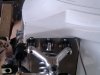
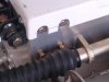
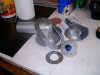
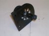
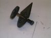
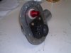
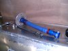
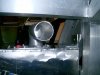
Roll over valve's. Here's my solution for a roll over valve. After looking at a lot of stuff on the ATL and Fuelsafe websites and talking to a couple of other racers I came up with this.
The valve is made of steel and fits the same bolt on configuration as a ATL flap valve. I didn't use it because it was quite stiff plastic and I don't think that the volume of fuel in the fill tube would open it. I think they are intended for fill cans or dry break fill plates.
Anyway the one I made is very similar to one I saw in a sprint car fuel cell. It really slaps closed when inverted and the valve is quite heavy being made of 1/4" steel and it seals quite well.
In any case the entire valve assemble can be removed from the fill plate and modified later if necessary.
Attachments
Howard Jones
Supporter
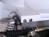
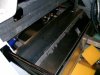
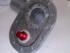
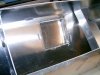
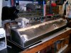
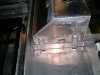
The fuel tank is pretty much done at this point. All that is left to do it drill some mounting holes in the chassis tubing, mount the fill cap nossle, and connect the tank fill plate to the fillcap nossle with some hose.
As you can see everything is removable from the tank and the tank can be removed from the car through the cover behind the seats. I intend to capture the heads of the mounting bolts so that this becomes a one man job with one 1/2 inch wrench. a screwdriver for the band clamps and AN-8 fitting wrench.
Just pull the seats, the cover behind them and then the tank. Easy pezie.
Attachments
-
 HPIM0903.jpg177 KB · Views: 542
 -
 HPIM0904.jpg162.7 KB · Views: 544
 -
 HPIM0915.jpg146.2 KB · Views: 528
 -
 HPIM0906.jpg159.4 KB · Views: 534
 -
 HPIM0917.jpg213.9 KB · Views: 532
 -
 HPIM0918.jpg192 KB · Views: 546
 -
 HPIM0922.jpg159.4 KB · Views: 506
 -
 HPIM0919.jpg137.9 KB · Views: 514
 -
 HPIM0924.jpg167.5 KB · Views: 533
 -
 HPIM0920.jpg138.3 KB · Views: 520
Last edited:
Hi Howard,
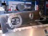
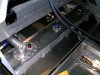
I see you have welded tabs on the tank to bolt to the chassis. Are you confident that the tank won't grow as it heats up and break the tab or the tank?
I was thinking of using the same tab design until I thought of the expansion the tank might have. I'm thinking about using straps as another SLC builder has done.
I haven't done the calculations to see how much longer the tank would get when heated up, but I plan to figure that out to get a better feel for the real risk of broken tabs.
-Will
Howard Jones
Supporter
I am going to mount them on 1/4 thick squares of multiple ply rubber. If you look close you can see the additional clearance in the mount location for the rubber isolation.
By the way this is how the two tanks in my GTD are mounted. The mounting tabs haven't cracked after 8 years.
Also I intend to seal the opening at the forward bulkhead of the engine room with a aluminum plate and insulation so I don't think there will be a lot of heat in the fuel tank area. At least not compared to the engine room.
Similar threads
- Replies
- 14
- Views
- 2K
- Replies
- 5
- Views
- 2K