Sorry in advance, I could not resist
That ole curmudgeon cracked me up!
Reminds me of ventriloquist Jeff Dunham's 'dummy' "Walter".........................................not to mention my own darned self!

Sorry in advance, I could not resist

Ah that's a job I still have to do, mind you I quite like the look of the mechanism but it will fail IVA I may make mine removable? Lookign great as always though Eddy
How did you get your stamped numbers to align so well, mine despite best efforts were all over the place. For what it is worth I just put some heat shrink over my gear lever and left the reverse lock out as it was for IVA, I may have just been lucky though.Gear linkage cover and shift gate made.

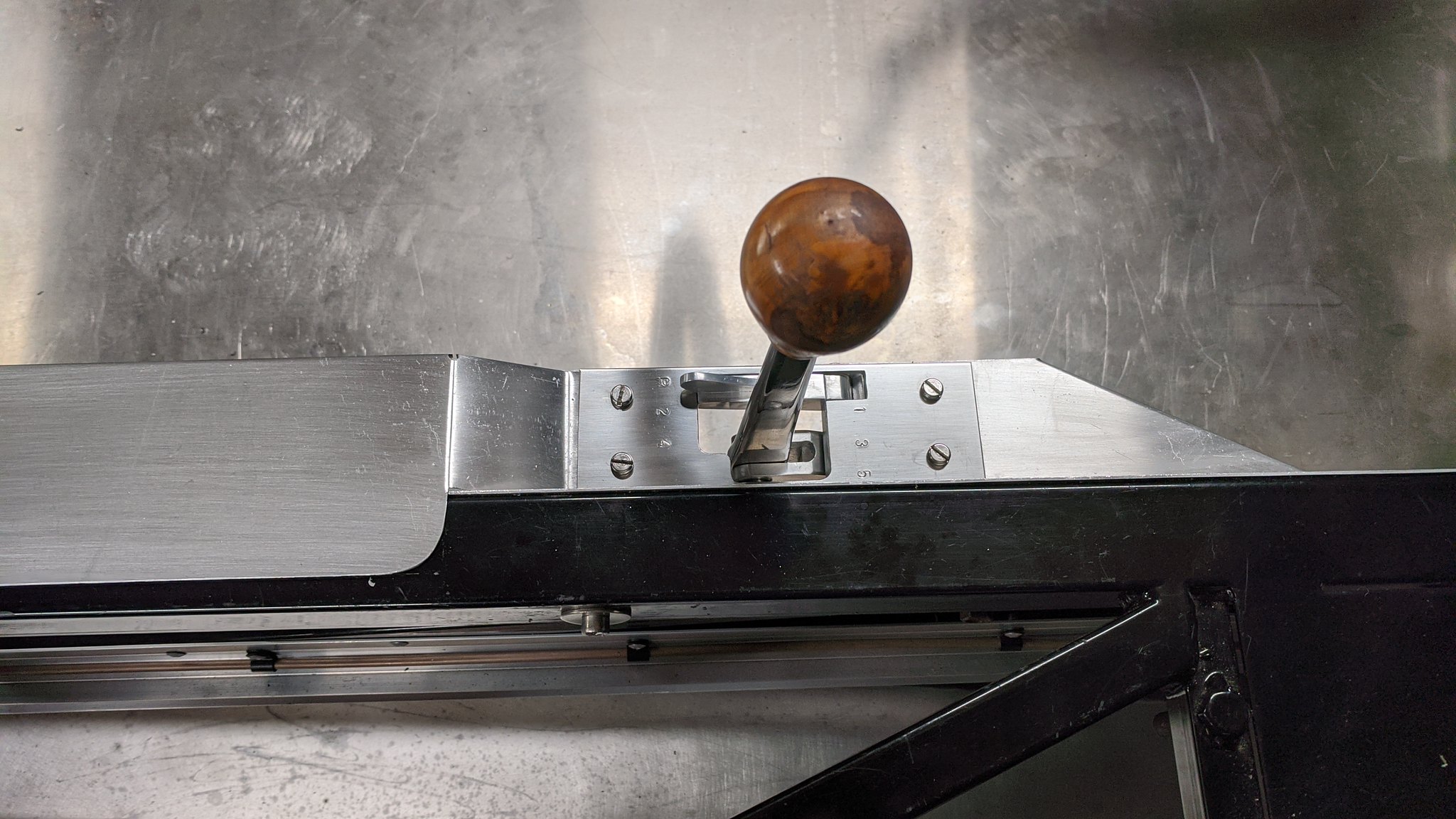
How did you get your stamped numbers to align so well, mine despite best efforts were all over the place. For what it is worth I just put some heat shrink over my gear lever and left the reverse lock out as it was for IVA, I may have just been lucky though.


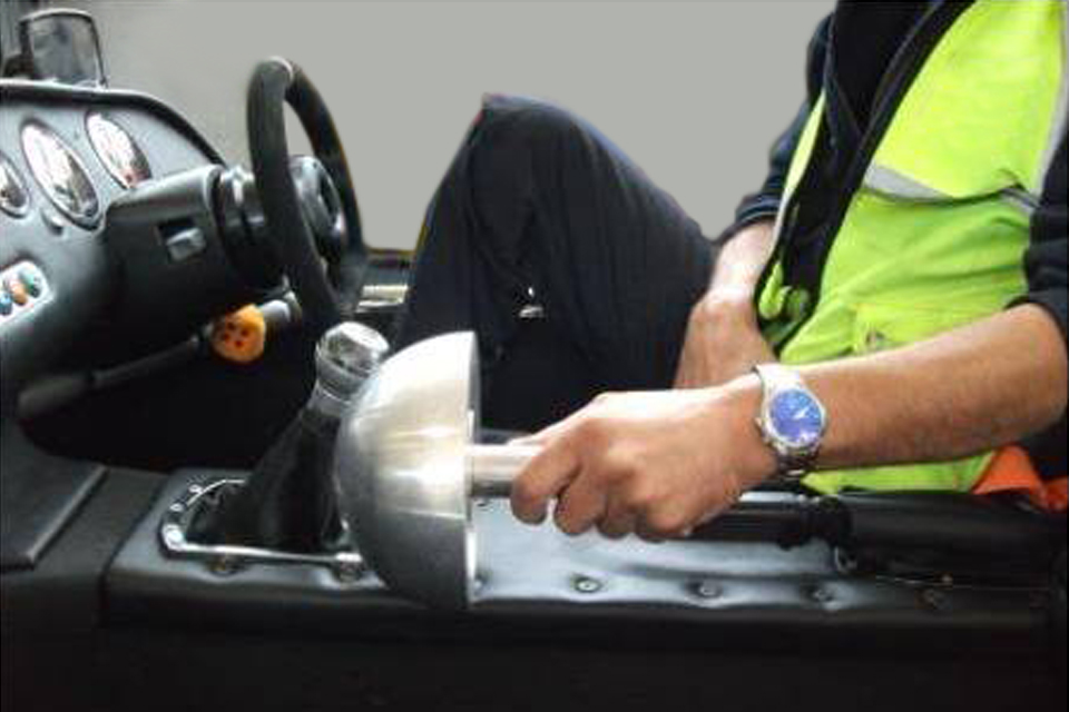
I think pedal be will be fine, frankly if you head hits that there are worse things to worry about !!! I was thinking on the gear shift as to the internals of the mechanism itself, others may have more knowledge but I think it has to be covered as its a pinch trap?
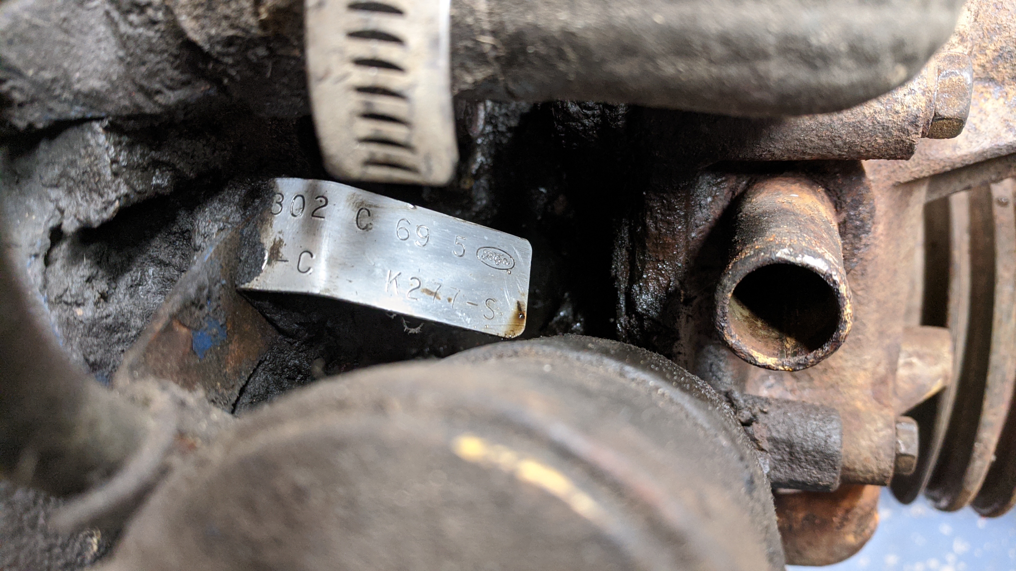
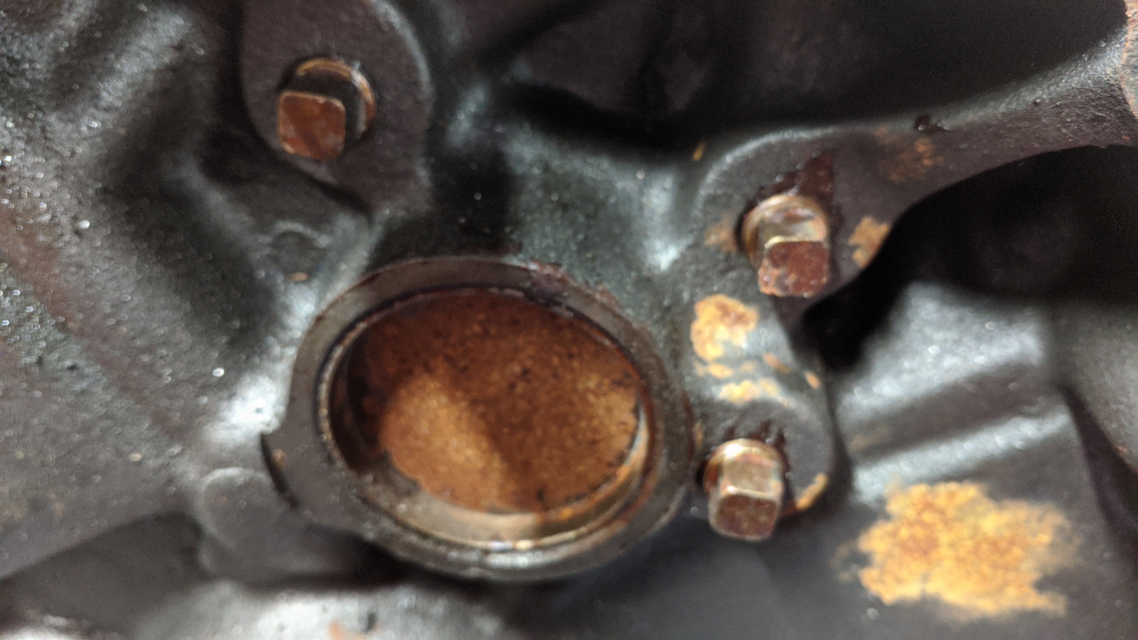
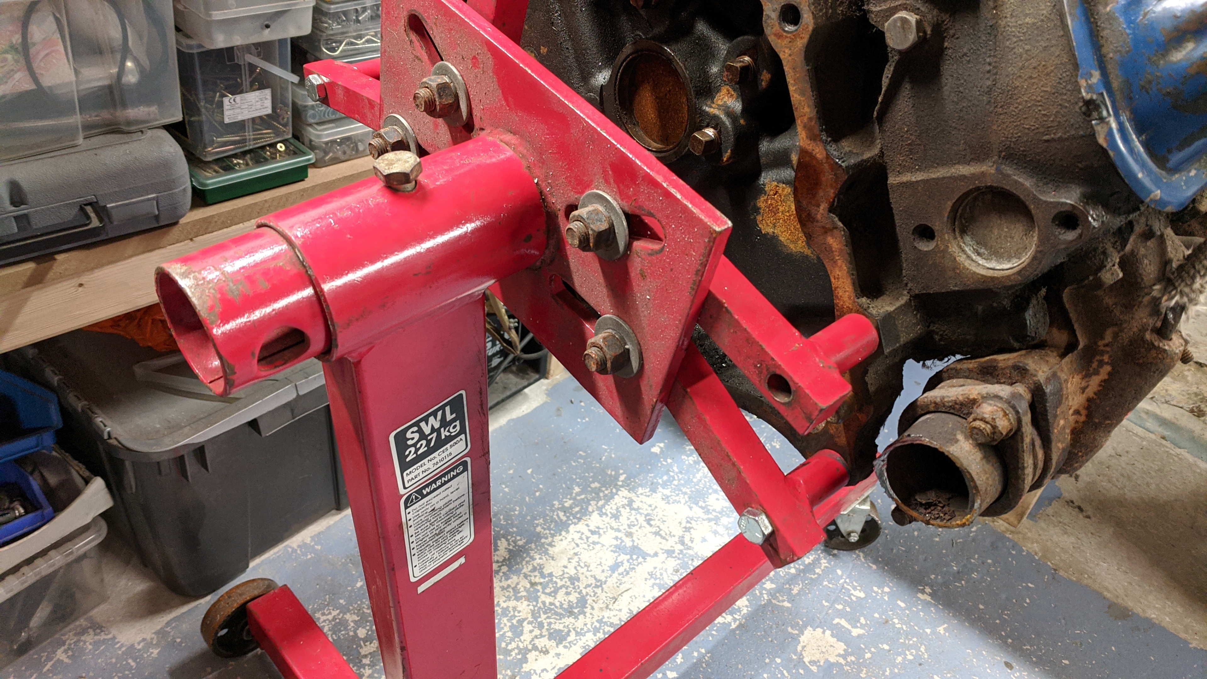
Where do you find such things, ive been looking for agesOh....and I appear to have bought a 1969 Ford small block 302 cubic-inch V8 engine. Complete, containing relatively clean oil and fresh coolant, so fingers crossed.

Thanks very much for pointing me in the right direction, got me thinking about what you would do if had bought a set of square punchesIt would have been much easier if I'd bought a square-section set of punches, with the letters aligned to the punch face:-
") . Looks like your idea of a jig is also the answer, I have over winter to attempt the same https://www.instructables.com/Jig-for-Punching-or-Stamping-Letters-Straight/
. Looks like your idea of a jig is also the answer, I have over winter to attempt the same https://www.instructables.com/Jig-for-Punching-or-Stamping-Letters-Straight/If it helps, I've been looking for 3 years, too. Check with Mark Gaskins at "Obsolete Fleet". He brings motorcycles in from the US, but has recently started adding a few engines to his containers. No affiliation, no endorsement, just another possible source.Where do you find such things, ive been looking for ages


")