Stephan's SLC Build Log

Stephan E.

Supporter
The fine engineers at Mercury did not cut any corners when it comes to providing serious hardware with their engines. I love working with the Deutsch and Delphi connectors which come with the engine. While running the engine harness I eventually reached the first interconnect. I did my best to make this look good and came up with fabricating a bracket for the watertight bulkhead which will connect to the ECU harness.
 

Attachments

  • Electrical_Engine_10.jpg
    Electrical_Engine_10.jpg
    425 KB · Views: 507
  • Electrical_Engine_11.jpg
    Electrical_Engine_11.jpg
    525.6 KB · Views: 480
  • Electrical_Engine_12.jpg
    Electrical_Engine_12.jpg
    379.3 KB · Views: 492
  • Electrical_Engine_13.jpg
    Electrical_Engine_13.jpg
    264.9 KB · Views: 395
  • Electrical_Engine_14.jpg
    Electrical_Engine_14.jpg
    586.4 KB · Views: 384
Last edited:

Stephan E.

Supporter
Since I do not have a mechanical water pump I also do not have an accessory drive. I had to prototype my own alternator belt tensioner, turned the spacers out of 316 SS with an enlarged base to distribute the stress on the engine block. The hardware is all metric 12.9 grade, fully engaged inside the M10 threads the block is providing. This assembly is rock solid even 3" out from where others are. The belt length is now only 1/3 of what a standard LS accessory belt is. I opted for the Powermaster Alternator. The performance sheet that came with it is showing 109 Amp at idle and a 171 Amp max. output. I think that will do.
 

Attachments

  • Alternator_1.jpg
    Alternator_1.jpg
    335 KB · Views: 449
  • Alternator_2.jpg
    Alternator_2.jpg
    323.7 KB · Views: 381
  • Alternator_3.jpg
    Alternator_3.jpg
    266.1 KB · Views: 446
  • Alternator_4.jpg
    Alternator_4.jpg
    272.7 KB · Views: 495
Last edited:

Stephan E.

Supporter
I wanted to share this alternate approach of fitting an SB4 engine into a SLC chassis. Here it is done on a Falcon F7 which is using an SLC base and wearing a different dress over it.This owner decided to go with water pump and accessory drive in place and had to cut and weld the living daylight out of that poor car. Also this car is not for the faint hearted. It has received Garrett twin turbos on top of the 750 stock ponies, Holley ECU, lower compression pistons.... New output, "Astronomical units"
 

Attachments

  • Falcon SB4 cut away_1.jpg
    Falcon SB4 cut away_1.jpg
    309.6 KB · Views: 831
  • Falcon SB4 cut away_2.jpg
    Falcon SB4 cut away_2.jpg
    324.1 KB · Views: 968
Last edited:

Stephan E.

Supporter
I spent some time with the factory center console. I was able to modify it to be used with the Audi R8 shifter. Still needs some finishing but I think the pictures are showing what it will be when done. Not sure if I will cover it with same Alcantara which are on the Tillets or do Hydro transfer printing to use the same carbon finish to match the tub. I molded in a concentric insert for the shifter gate, the bottom was widened about an inch and the top about 1/2 inch. The tail which meets the spine on the tub is still factory width. Everything fits nicely and the shifter has plenty of room without interfering with the seats and eliminating all the Audi hardware for the shifter gate. If I find some nice cup holders I may add them.
 

Attachments

  • Center console_1.jpg
    Center console_1.jpg
    266.7 KB · Views: 499
  • Center console_2.jpg
    Center console_2.jpg
    433.6 KB · Views: 475
  • Center console_3.jpg
    Center console_3.jpg
    535.7 KB · Views: 414
  • Center console_4.jpg
    Center console_4.jpg
    861.5 KB · Views: 430
  • Center console_5.jpg
    Center console_5.jpg
    371.2 KB · Views: 439
  • Center console_6.jpg
    Center console_6.jpg
    331.8 KB · Views: 404
  • Center console_7.jpg
    Center console_7.jpg
    446 KB · Views: 447
  • Center console_8.jpg
    Center console_8.jpg
    655.3 KB · Views: 463
Last edited:

Stephan E.

Supporter
Here is the final version of the intake system. Everything is tight but it went in as planned. Filler neck clears and still room for the side exhaust. Fitted heat shields for the filters which will still receive thermal barrier material.
 

Attachments

  • Intake system_1.jpg
    Intake system_1.jpg
    237.5 KB · Views: 465
  • Intake system_2.jpg
    Intake system_2.jpg
    364.7 KB · Views: 498
  • Intake system_3.jpg
    Intake system_3.jpg
    529.1 KB · Views: 504
  • Intake system_4.jpg
    Intake system_4.jpg
    548.8 KB · Views: 436
  • Intake system_5.jpg
    Intake system_5.jpg
    333 KB · Views: 429
  • Intake system_6.jpg
    Intake system_6.jpg
    495.7 KB · Views: 562
Last edited:

Joel K

Supporter
Here is the final version of the intake system. Everything is tight but it went in as planned. Filler neck clears and still room for the side exhaust. Fitted heat shields for the filters which will still receive thermal barrier material.

Nice job Stephan, engine bay is coming along well. Nice and clean considering how much engine you have packed in there.
 

Stephan E.

Supporter
Thanks Joel,

There is/was more cramming stuff into that engine bay. Here is the revamped fuel system. Now good to 1600 HP. I went with components from Radium and Hyperfuel (very spacy). The surge tank went external due to serviceability into dead space and is removable with two screws. I found this multi fuel pump FPR and added a 10 Micron washable stainless strainer and build in check valve. Fuel lines running under the manifold since there is a recess milled into the valley plate with plenty of room. The first stage pump and pre-filter remained inside the compartment. A rollover/vent valve was added to the second upper port as well as decent disconnects from Delphi.
 

Attachments

  • Fuel system rev.1_1.jpg
    Fuel system rev.1_1.jpg
    255.6 KB · Views: 462
  • Fuel system rev.1_2.jpg
    Fuel system rev.1_2.jpg
    196.5 KB · Views: 442
  • Fuel system rev.1_3.jpg
    Fuel system rev.1_3.jpg
    253.5 KB · Views: 442
  • Fuel system rev.1_4.jpg
    Fuel system rev.1_4.jpg
    622.9 KB · Views: 464
  • Fuel system rev.1_5.jpg
    Fuel system rev.1_5.jpg
    482 KB · Views: 442
  • Fuel system rev.1_6.jpg
    Fuel system rev.1_6.jpg
    207.5 KB · Views: 437
  • Fuel system rev.1_7.jpg
    Fuel system rev.1_7.jpg
    435 KB · Views: 397
  • Fuel system rev.1_8.jpg
    Fuel system rev.1_8.jpg
    356.3 KB · Views: 434
  • Fuel system rev.1_9.jpg
    Fuel system rev.1_9.jpg
    304.3 KB · Views: 418
Last edited:

Stephan E.

Supporter
And while tube notching never really was one my favorite sports I think the outcome here is presentable. Ready for powder coating. I am indecisive about which color to chose. My favorites are satin black and chrome effect. Any suggestions? While designing this brace I considered the integration of this coolant expansion tank. All electrical components and fuse/relay box are fully accessible. Pardon the mess, I am still running wires and nothings is tied down or terminated.
 

Attachments

  • Cross Brace_10.jpg
    Cross Brace_10.jpg
    430.4 KB · Views: 429
  • Cross Brace_11.jpg
    Cross Brace_11.jpg
    264.4 KB · Views: 364
  • Cross Brace_12.jpg
    Cross Brace_12.jpg
    202.1 KB · Views: 415
  • Cross Brace_13.jpg
    Cross Brace_13.jpg
    228.9 KB · Views: 394
  • Cross Brace_14.jpg
    Cross Brace_14.jpg
    526 KB · Views: 428
  • Cross Brace_15.jpg
    Cross Brace_15.jpg
    657.4 KB · Views: 441
  • Cross Brace_16.jpg
    Cross Brace_16.jpg
    456.4 KB · Views: 438
  • Cross Brace_17.jpg
    Cross Brace_17.jpg
    429.6 KB · Views: 405
  • 20180726_170905.jpg
    20180726_170905.jpg
    304.4 KB · Views: 388
Last edited:

Joel K

Supporter
Great work and progress Stephan. As far as powdercoat goes, I like the black satin with a little sheen, or go with some metallic silver/grey to blend with the aluminum
 

Stephan E.

Supporter
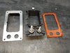
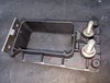
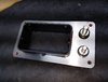
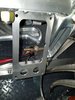
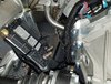
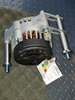
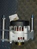
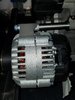
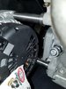
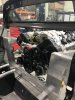
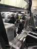
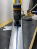
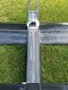
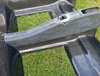
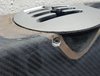
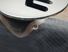
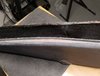
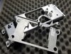
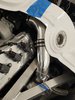
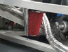
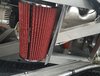
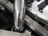
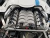
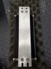
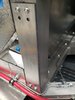
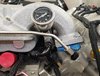
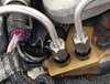
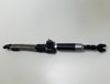
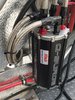
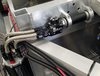
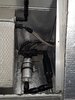
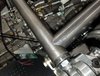
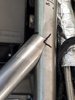
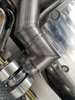
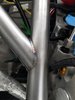
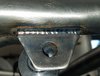
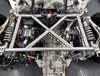
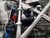
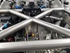
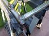
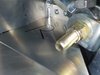
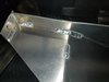
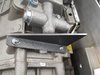
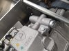
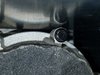
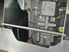
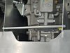
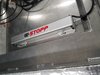
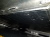
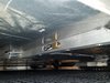
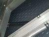
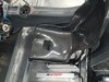
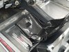
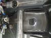
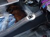
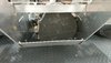
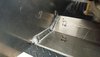
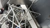
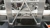
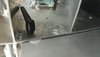
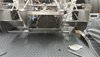
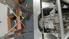
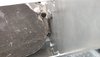
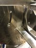
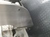
A few month back I started to look into solutions to eliminate the factory hardware for the rear diffuser and to remove all flexing and deflection. I think I finally found the final version of it. After looking for existing attachments points, it hit me. The transaxle is a fixed point in space, is strong and has plenty of hubs which are pre drilled and threaded. The casing will absorb the downforce, I have no worries there. All I can say that the diffuser does not move anymore, in any direction and is absolutely symmetrical and straight (took some massaging...). All dimensions were double checked and measured across the rear chassis. I also think its pretty too without the usage of massive hardware obstructing the view, taking the attention from other major components away. I chose 5/8 steel tubing with 1/8 wall and M12 bolts welded to a slanted bracket with 4mm material thickness. The clamping force is incredible. I installed the wing uprights because I needed to check for interference. I found that I still having 2mm between the passenger side upright and the closest bolt of the transaxle. The gussets are made from 3mm 6061-T6 and I continued stitch welding a la factory from the underside.
 

Attachments

  • 20180307_092356.jpg
    20180307_092356.jpg
    325.8 KB · Views: 432
  • 20180307_092612.jpg
    20180307_092612.jpg
    384.3 KB · Views: 431
  • 20180307_092652.jpg
    20180307_092652.jpg
    233.7 KB · Views: 412
  • 20180802_182130.jpg
    20180802_182130.jpg
    311.7 KB · Views: 423
  • 20180802_190420.jpg
    20180802_190420.jpg
    333.9 KB · Views: 364
  • 20180809_181157.jpg
    20180809_181157.jpg
    476.5 KB · Views: 380
  • 20180810_181122.jpg
    20180810_181122.jpg
    425 KB · Views: 395
  • 20180811_112127.jpg
    20180811_112127.jpg
    461.1 KB · Views: 387
  • 20180811_112210.jpg
    20180811_112210.jpg
    371.9 KB · Views: 401
  • 20180811_112216.jpg
    20180811_112216.jpg
    338.4 KB · Views: 439
Last edited:

Stephan E.

Supporter
I always had my concerns looking at where I initially placed the E-Stopp servo. I recently received word that a fellow SLC owner had a failing unit and was unable to reach it for repair or replacement. I am certain that can be resolved by using a different attachment method to the outer rail but I decided to relocate the whole system. After I finished the roughing of the center console I refitted the seats and tub to see where I am at with being center to the steering wheel. I noticed that the Tillets and factory console offering now a 6" opening left of the driver seat which was not so generous when I did the same with RCR stock seats. That is where I placed it. It will be made disappear with a carbon covering as an extension of the tub or the fire extinguisher will sit on top of it. Nevertheless it is fully serviceable. The factor that the brackets and cables could be caught was at least reduced by a skid channel behind the seat drop which is still higher than the actual drop. The harware went in there with a side opening to adjust the cables and rod length. All fully tested and working.
 

Attachments

  • 20180628_211111.jpg
    20180628_211111.jpg
    354.2 KB · Views: 391
  • 20180617_141642.jpg
    20180617_141642.jpg
    301.9 KB · Views: 407
  • 20180628_210642.jpg
    20180628_210642.jpg
    256.4 KB · Views: 347
  • 20180811_170042.jpg
    20180811_170042.jpg
    271.6 KB · Views: 426
Last edited:

Stephan E.

Supporter
Just a few more pictures on the available space for the E-Stopp placement.
 

Attachments

  • 20180825_192731.jpg
    20180825_192731.jpg
    482 KB · Views: 372
  • 20180825_192758.jpg
    20180825_192758.jpg
    477.3 KB · Views: 408
  • 20180825_192912.jpg
    20180825_192912.jpg
    503.6 KB · Views: 428
  • 20180825_162149.jpg
    20180825_162149.jpg
    443.5 KB · Views: 470

Stephan E.

Supporter
Got some more work done on the diffuser and the only two things left to is the figuring out the exact spot for the bearing hubs for the rear shell hinges and powder coating. I used M8 ratchet clamping handles and 10mm shoulder bolts. I have 1.5mm clearance between the diffuser and wing uprights to accommodate Teflon spacers after coating to prevent scratching and rattle free fitment. The billet cross bracing, welded plate mount, and added welded wing under the transaxle summing up some real nice strength. The slider stops have received some weld washers to hold the shoulder bolts solid. No tools required to lock/unlock the wing. I think it turned out really well.
 

Attachments

  • DSC_0038.JPG
    DSC_0038.JPG
    297.6 KB · Views: 499
  • DSC_0039.JPG
    DSC_0039.JPG
    224.5 KB · Views: 471
  • DSC_0065.JPG
    DSC_0065.JPG
    348.3 KB · Views: 509
  • DSC_0067.JPG
    DSC_0067.JPG
    312.5 KB · Views: 509
  • DSC_0069.JPG
    DSC_0069.JPG
    191.9 KB · Views: 426
  • DSC_0070.JPG
    DSC_0070.JPG
    333.6 KB · Views: 493
  • DSC_0071.JPG
    DSC_0071.JPG
    346.4 KB · Views: 484
  • DSC_0072.JPG
    DSC_0072.JPG
    338 KB · Views: 429
  • mms_20180830_181225.jpg
    mms_20180830_181225.jpg
    164.9 KB · Views: 365
  • 20180914_194627.jpg
    20180914_194627.jpg
    250.6 KB · Views: 382

Stephan E.

Supporter
Hi Markus,

I was traveling for business for the last few months. Finishing up my last trip for the year this week and I am looking forward to spending time with my SLC...

Update will follow shortly.

Cheers
 
Back
Top