
You are using an out of date browser. It may not display this or other websites correctly.
You should upgrade or use an alternative browser.
You should upgrade or use an alternative browser.
the Steinard MK3 takes shape
- Thread starter kaspa
- Start date
Something I cant say ive seendone, but I was having a think and thought why not it should work and eliminate the rod end in bending scenario, so I made a new control link and removed the shock so I could try it through full range of travel, and it works perfectly with no change in the numbers, well almost , my roll center has dropped another 5mm, so what do you think.

cheers kaspa

cheers kaspa
John,
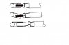
Top drawing is your first setup using a heim joint at front of that compression strut.
Middle is likely scenario in use which could cause failure of heim joint &/or mounting tab on upper link.
Bottom is simple theaded end in place of heim that still uses the bolt but prevents rotation of top link.
Only thing possibly against the mounting on top of upright which puts a bending moment on the bolt which comes back to bolt size choice.
Attachments
very true Russ but I only loose less than an inch, or a couple of degrees, so not all that bothered, it wont be doing U turns in suburban streets any time soon.
so today I started on the rear suspension, got one side almost done then ran out of both tube and rod ends bugger, so the brakes have come on until I can get some more bits.
but this is what I did today.

cheers Kaspa
so today I started on the rear suspension, got one side almost done then ran out of both tube and rod ends bugger, so the brakes have come on until I can get some more bits.
but this is what I did today.

cheers Kaspa
So today I started on the alloy, 2mm for both pontoons and floor, and wasn't it fun trying to get the sides to roll, took 4 straps and every clamp I own, but I got it eventually with out any distortion or marks thank god.

Then the task of getting it off the table, turning it over and putting it back on the table, wasn't easy but I got there and again nary a scratch to be seen thank god.

So now I can start on the interior panels and rear bulkhead.
cheers Kaspa

Then the task of getting it off the table, turning it over and putting it back on the table, wasn't easy but I got there and again nary a scratch to be seen thank god.

So now I can start on the interior panels and rear bulkhead.
cheers Kaspa

Hi Mate, Have you changed your plan about the reverse "A" arm for the bottom link??
I think the twin link system will make it slightly easier when doing "Toe in" adjustments. The M20 has long bottom links and this helps the wheel stand up straight when the chassis rolls in the corners. When you look at video's its surprising how much movement they had.
The box has arrived and I will be into it soon, I'm still making core prints and core box's for the new uprights. If you know someone who would be interested in my solid uprights (my car ones) give me a bell as I may offer my whole set (front as well with the pin drive set up)
You are doing a great job, love watching all your projects.
Cheers Leon
Had one of those days where this time a little looks like a lot, doesn't happen very often, but today I made up the dash panel and the top for the right hand side pontoon.

Then made up my steering shaft and got that all sorted, managed to make my own 9/16 x 36 spline spud for the end of the tube to fit the Escort uni

Then at the dash end I used a 3/4 Aurora alloy rod end I had and jobs done, as good as a bought one.

all in all a good days effort.
And then the icing on the cake was my wheel centers arrived from Fran, and boy are the a work of art or what, pin drive Lola wheels

cheers Kaspa
Last edited:
WOW,
I mean, most of us have at least band saws, drill presses and grinders, others have nice equipment like press breaks,finger breaks,etc, and the lucky ones have mills,lathes,surface grinders,etc... However not many of us are able to cut our own splines!!! Damn,now I have to hit the auctions again for more equipment and peruse YouTube to learn how to do that!!
John,as always, I look to you clever dudes down under for inspiration to "Get it done" by doing most everything in house with what you have.
What DID you use to cut the splines?? A horizontal mill and a rotating index collet with a slitting cutter?
Hi Dave, no, apart from a drill press and a 4 inch grinder I have a small hobby lathe I shouted myself a couple years ago, so after sitting on my thinking stool for a few mins I spotted a piece of round bar lying in the bed so I thought to my self ill have a go, so I ground up an old lathe tool into a bit of a V put my rod in the chuck and used my cam degree wheel, as I needed 36 splines, so that's 5 deg spaces so used the DTI as a pointer and just wound the cutter in and out by hand till I had a groove, then tuned the chuck 5 deg and did it again etc , and after going around 3-4 times I had some sort of resemblance to a spline, and when I tried it, all it took was a few taps and in she went and it cleaned up the shape quite nicely, admittedly it took about an hr, but it did the job and saved me a small fortune and a lot of time, I wouldn't try it on anything much bigger though.
cheers Kaspa
cheers Kaspa
")
have made a little bit more progress, in so much as I redesigned the shifter that I did for the 5000 and got it all fitted, it utilizes a flanged linier bearing at the front and a barrel linier bearing at the rear where it goes through the chassis, which give a really nice smooth feel to the action.


then today I made a simple reverse lock out mechanism, its just a simple spring loaded pin which will slide along a strip of 6mm alloy that I will fit tomorrow.

next the dash.
kaspa


then today I made a simple reverse lock out mechanism, its just a simple spring loaded pin which will slide along a strip of 6mm alloy that I will fit tomorrow.

next the dash.
kaspa
Similar threads
- Replies
- 9
- Views
- 671
- Replies
- 10
- Views
- 2K