I'm checking in too and I can't see the pictures. Any idea why? I tried last night to read the thread from the beginning and I had the same problem.

You are using an out of date browser. It may not display this or other websites correctly.
You should upgrade or use an alternative browser.
You should upgrade or use an alternative browser.
Toms RCR 40 Trackracer
- Thread starter EGLITOM
- Start date
- Status
- Not open for further replies.
Dean , On the first pages of the thread some links to pics are lost. But there should be no issue on later pages ( as of page 3 or 4).
Planning on changing from my 750 Holley setup to a IDA 48 setup.
Im starting on preparing my IDA 48 setup now. Collected two pairs of used IDA 48. one pair has not seen fuel at all and the other one only for 1000km, Both are in could condition and would only need a cleanup. But also would like to optimise flow as good as possible, so aux venturis will be cleaned of all the casting burres and polished. Transition from Airhorn to aux venturi will be smoothed ( camfering the auxventuri ID to the airhorns ID). Size 40 venturi chokes will be polished and installed. They may be a bit small for my engine, but will give them a try first and see what the dyno tells me. Throttleblade screws will be replaced by countersunk ( earlier type) ones and the overstanding threads shorted as far as possible to still retain the safety function against loosening.
INtake will be portmatched to carbs and head.
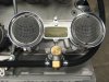
Here is a pic of the mockup yesterday night
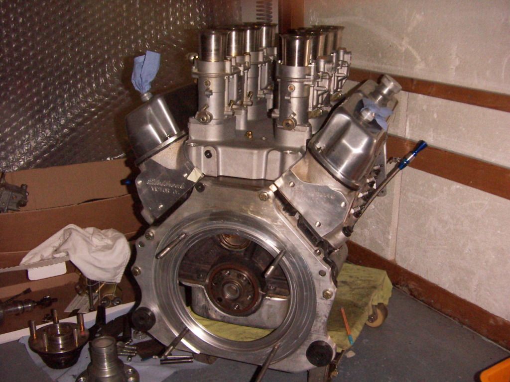
LInkage will be a center rotating linkage with symetrical push arms to both sides. Idle speed adjustment will be done on the center lever of the linkage not on the carbs, to take out any play in any load situation. Throttle cable will be the same as on the holley setup, coming in from the backside of the engine into the center.
I´m also going to use the same aeromotive fuel pressure regulator, only building new feed lines to the Webers. This regulator has an inletsize of 8AN and two AN6 outlets of which each one will feed one bank, thus no necessity to have a fuel line running around the back of the carbs. Original style Turkey pan will be used. For car shows open velocity stacks are the plan, for regular driving i´m going to use the paired K&N filters which have a specific bottom plate fitting the IDA´s. Would love to go with their 4,5" high setup , but not quite sure yet if i have the space for them.
http://www.knfilters.com/search/product.aspx?prod=56-1220
My current disszy will not fit , it does not clear the intake heightwise, would need a disszy which has a 1/2= longer shaft. Have not yet checked the MSD side for availability.
TOM
Planning on changing from my 750 Holley setup to a IDA 48 setup.
Im starting on preparing my IDA 48 setup now. Collected two pairs of used IDA 48. one pair has not seen fuel at all and the other one only for 1000km, Both are in could condition and would only need a cleanup. But also would like to optimise flow as good as possible, so aux venturis will be cleaned of all the casting burres and polished. Transition from Airhorn to aux venturi will be smoothed ( camfering the auxventuri ID to the airhorns ID). Size 40 venturi chokes will be polished and installed. They may be a bit small for my engine, but will give them a try first and see what the dyno tells me. Throttleblade screws will be replaced by countersunk ( earlier type) ones and the overstanding threads shorted as far as possible to still retain the safety function against loosening.
INtake will be portmatched to carbs and head.
Here is a pic of the mockup yesterday night
LInkage will be a center rotating linkage with symetrical push arms to both sides. Idle speed adjustment will be done on the center lever of the linkage not on the carbs, to take out any play in any load situation. Throttle cable will be the same as on the holley setup, coming in from the backside of the engine into the center.
I´m also going to use the same aeromotive fuel pressure regulator, only building new feed lines to the Webers. This regulator has an inletsize of 8AN and two AN6 outlets of which each one will feed one bank, thus no necessity to have a fuel line running around the back of the carbs. Original style Turkey pan will be used. For car shows open velocity stacks are the plan, for regular driving i´m going to use the paired K&N filters which have a specific bottom plate fitting the IDA´s. Would love to go with their 4,5" high setup , but not quite sure yet if i have the space for them.
http://www.knfilters.com/search/product.aspx?prod=56-1220
My current disszy will not fit , it does not clear the intake heightwise, would need a disszy which has a 1/2= longer shaft. Have not yet checked the MSD side for availability.
TOM
Last edited:
Tom:
Lots of material in that post. Want to comment on just one: the air filters.
Those K and N are a excellent idea. But for "show", nothing like the open intakes.
I have open mesh screens on mine currently, and they cost about 20 horsepower. Of course they are easily popped off.
So that leads to some thoughts.
First, if one drives the GT40 2000 - 3000 miles per year on clear days and paved roads, just how much engine wear are we really talking about if one uses the 'tea strainers' rather than a serious filter.
Second, can more frequent oil changes make up for the increased dust sucked in through the carbs?
Third, swapping out the K and N for the stock intakes is fine for show, but at five screws per carb, total of 20, probably not something one would do very often.
Finally, it would be interesting to do a dyno comparison between the K and N and the stock horns. Even different shaped horns can affect the performance of the Webers.
You can see where I am going with this. If the life of an expensive engine is seriously threatened by using just the strainers for even occasional use, . . . . . Enough said.
Attachments
Dear Chuck
i see what you are saying. Don´t think that the 4,5" K&N will make a difference in performance ( unlike the teastrainers, which in fact are not a filter , rather only a debris protection and i´m convinced they would cost me more than 20 HP especially on 6000 RPMS and above)
This is the linkage concept i´m thinking of. As previously mentioned accelerator cable will come in from the rear of the engine. No idle speed screws will be used on carbs, only one on the linkage. This way all the returnspring loads take out any play of the linkage, as everything is purely on push loads.
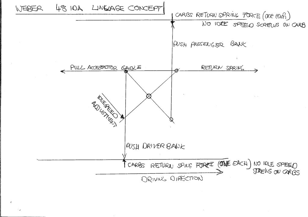
Still not quite sure if i should do the accelerator cable lever as a lever or a cam type ( with the pull wire rolling along) for smoother, equal speed action.
What you think?
TOM
i see what you are saying. Don´t think that the 4,5" K&N will make a difference in performance ( unlike the teastrainers, which in fact are not a filter , rather only a debris protection and i´m convinced they would cost me more than 20 HP especially on 6000 RPMS and above)
This is the linkage concept i´m thinking of. As previously mentioned accelerator cable will come in from the rear of the engine. No idle speed screws will be used on carbs, only one on the linkage. This way all the returnspring loads take out any play of the linkage, as everything is purely on push loads.
Still not quite sure if i should do the accelerator cable lever as a lever or a cam type ( with the pull wire rolling along) for smoother, equal speed action.
What you think?
TOM
Tom,
I have the cam type on my TWM injectors, and it makes a smooth path for the cable to follow, and you can't feel any drag on the cable at all. I would think the lever would cause some bind as the cable is pushed further out in the arc of the lever, creating a drag on the cable. Worst case senario, would make a sticky throttle and fear of it becoming stuck at WOT. I guess if the mount for the cable housing is far enough back it would aleviate some of the bind. The other down side is that this would crate a rub on the cable creating wear and possible breakage. My vote is for the cam.
Bill
Hi Tom,
I think you will not like the end result if you eliminate the idle speed screws. As you linkage tolerance opens up, you will have one or more carbs whose throttle blades go fully closed. Now while this will result in poor idles characteristics, it will do something far worse. The throttle blades will very quickly wear into the throttle bodies themselves.
I too like the cam as it will remove any quick action from the movement of the cable and make it 100% linear with pedal movement if you design the cam properly.
Hi Tom,
I think you will not like the end result if you eliminate the idle speed screws. As you linkage tolerance opens up, you will have one or more carbs whose throttle blades go fully closed. Now while this will result in poor idles characteristics, it will do something far worse. The throttle blades will very quickly wear into the throttle bodies themselves.
I too like the cam as it will remove any quick action from the movement of the cable and make it 100% linear with pedal movement if you design the cam properly.
But exactly this has been the idea to eliminate. If one relies on the individual idle speed screws of each carb, you would have to overcome the tolerances first at every action, because the levers rest on the idle speed screw and every tension will be taken out of the linkage in idle. When you step on now, you have to tension the linkage first before getting any action.
Without the idle speed srcrews every likely tolerance will be taken out of this equation, because everything is on push and thus the tolerances are "compressed out".
The tolerances will open up in any case, but without idle speed screws on the carbs your realise it and just need to readjust.
If one is using highquality rodends and good material and well dimensioned linkage arms and rods, a good solind base with playfree bearings it should be able to achieve a good result. Thats also the reason why i decided to built that linkage by myself.
The big advantage i see is, that i need to adjust one idle speed screw and thus can set my idle pretty quick.
Everything else should be ok anyway ( correct idle mixture, correct blade position, perfect synchro).
If it not works out like intended, i always can add those individual idle speed screws, or just keep them in as a emergency block to avoid the blades working into the body, but not influencing the idle.
Thanks for the input on the cam.
TOM
Tom
On both the IDF and IDA systems I have had one single idle screw was used. The other three were simply removed. The connecting linkage is adjusted to match the flow amd then that single screw is to set the idle speed, in conjunction with the mixture screws on each carb.
From your description that sounds like what you are planning.
Been somewhat bemused that TOM the Racer wants to put some restrictor carbs on his motor") FWIW here's my thoughts on what your doing...
FWIW here's my thoughts on what your doing...
Since your now effectively going to have an eight barrel carb setup on a 'mini' plenum due to the manifold you have chosen ( at least during the idle/low air requirement phase of engine operation ) you might be better to install an adjustable 'Air Valve' into the plenum and use that to control your idle speed . I still think you will need to keep the individual idle speed screws if only to get a base setting for the throttle blades, once you attain that you should be able to loctite those idle speed screws and all further idle speed adjustments done on the 'Air Valve' & mixture screws. This would work similar to the 'Idle Easy' setup on many late model Holley derivatives.
The only possible negative I see in your proposed setup is the possibility of fuel puddling in the plenum during low speed operation due to your cam specs..this may manifest itself in operation once RPM rises & the puddled fuel is drawn back into the main runners to give you a false 'Rich' condition..
I will watch with interest!!
FWIW here's my thoughts on what your doing...Since your now effectively going to have an eight barrel carb setup on a 'mini' plenum due to the manifold you have chosen ( at least during the idle/low air requirement phase of engine operation ) you might be better to install an adjustable 'Air Valve' into the plenum and use that to control your idle speed . I still think you will need to keep the individual idle speed screws if only to get a base setting for the throttle blades, once you attain that you should be able to loctite those idle speed screws and all further idle speed adjustments done on the 'Air Valve' & mixture screws. This would work similar to the 'Idle Easy' setup on many late model Holley derivatives.
The only possible negative I see in your proposed setup is the possibility of fuel puddling in the plenum during low speed operation due to your cam specs..this may manifest itself in operation once RPM rises & the puddled fuel is drawn back into the main runners to give you a false 'Rich' condition..
I will watch with interest!!
Jac Mac:
What took you so long, i expected this post much earlier and your feedback is always highly appreciated:thumbsup:
Restriction: Mhhmm , believe you are right, but i will try everything not to. Will give it a try with the standard Weber parts first.
But if they not achieve the desired result, i´m going to try this
Isn't it time for a NEW racing carburetor? • Speed Talk
modifying a carburetor to work without booster venturi • Speed Talk
some pictures of this setup
Login • Speed Talk
They are also readily available ( although in a bit simpler version), but according the the people using them work great.
[ame]http://www.youtube.com/watch?v=XzomjALtdeE[/ame]
More custom designed products from JPM

Admit it is a bit lazy from idle.
Last resort is than to increase the butterfly size.
IDLE. With the 4bbl setup i´m currently able to achieve a 1200 - 1400 RPM idle. If it is a bit higher with the IDA´s i don´t mind, but at that speed i hope the fuel puddling will be not big of an issue. Will see and kind of like the challenge.
TOM
What took you so long, i expected this post much earlier and your feedback is always highly appreciated:thumbsup:
Restriction: Mhhmm , believe you are right, but i will try everything not to. Will give it a try with the standard Weber parts first.
But if they not achieve the desired result, i´m going to try this
Isn't it time for a NEW racing carburetor? • Speed Talk
modifying a carburetor to work without booster venturi • Speed Talk
some pictures of this setup
Login • Speed Talk
They are also readily available ( although in a bit simpler version), but according the the people using them work great.
[ame]http://www.youtube.com/watch?v=XzomjALtdeE[/ame]
More custom designed products from JPM
Admit it is a bit lazy from idle.
Last resort is than to increase the butterfly size.
IDLE. With the 4bbl setup i´m currently able to achieve a 1200 - 1400 RPM idle. If it is a bit higher with the IDA´s i don´t mind, but at that speed i hope the fuel puddling will be not big of an issue. Will see and kind of like the challenge.
TOM
Last edited:
Tom
On both the IDF and IDA systems I have had one single idle screw was used. The other three were simply removed. The connecting linkage is adjusted to match the flow amd then that single screw is to set the idle speed, in conjunction with the mixture screws on each carb.
From your description that sounds like what you are planning.
Almost, except that i want to place the idle speed screw on the center linkage lever to have equal load distribution left to right bank and not pushing all the returnsprings to one single carbs idle speed screw. Will be much less force on the carb levers ( only the one of the carbs return springs, not the one of the center lever return spring). (check the sketch above).
Have had some bad experience with the linkage (stock redline crossbar system) of my sons beetle and are right in the middle of reworking it as well. Rods and levers are just to weak and badly designed, returnspring forces to much, so it always run out of synchro and it is difficult to manage an even synchro over the whole rpm range.
Therefore i would like to do it correctly on my Ford from the beginning.
THanks
TOM
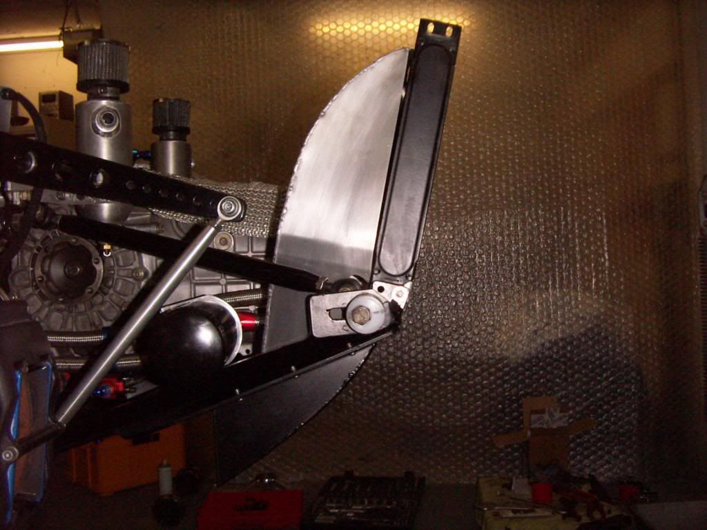
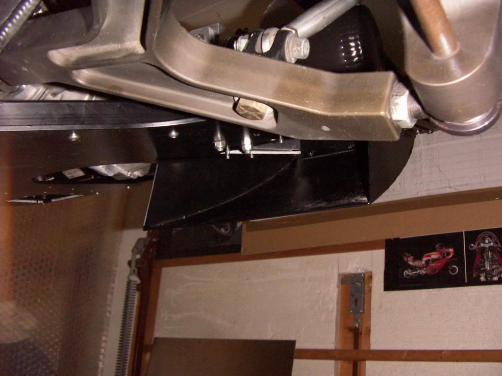
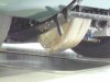
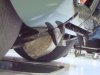
New engine mounts
I used the usual hard polymounts, but still they allowed the engine to move to much.
I fabed new ones out of angle stock, rectangular tubing and round tubing. ROund tubing filled with Polyurethan bushing and rectangular one equipped with adjustable strut to the adapterplate. Stainless, electropolished.
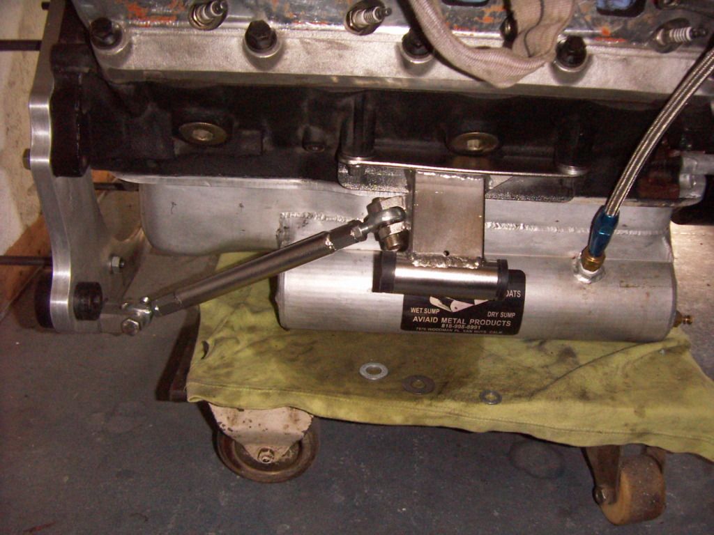
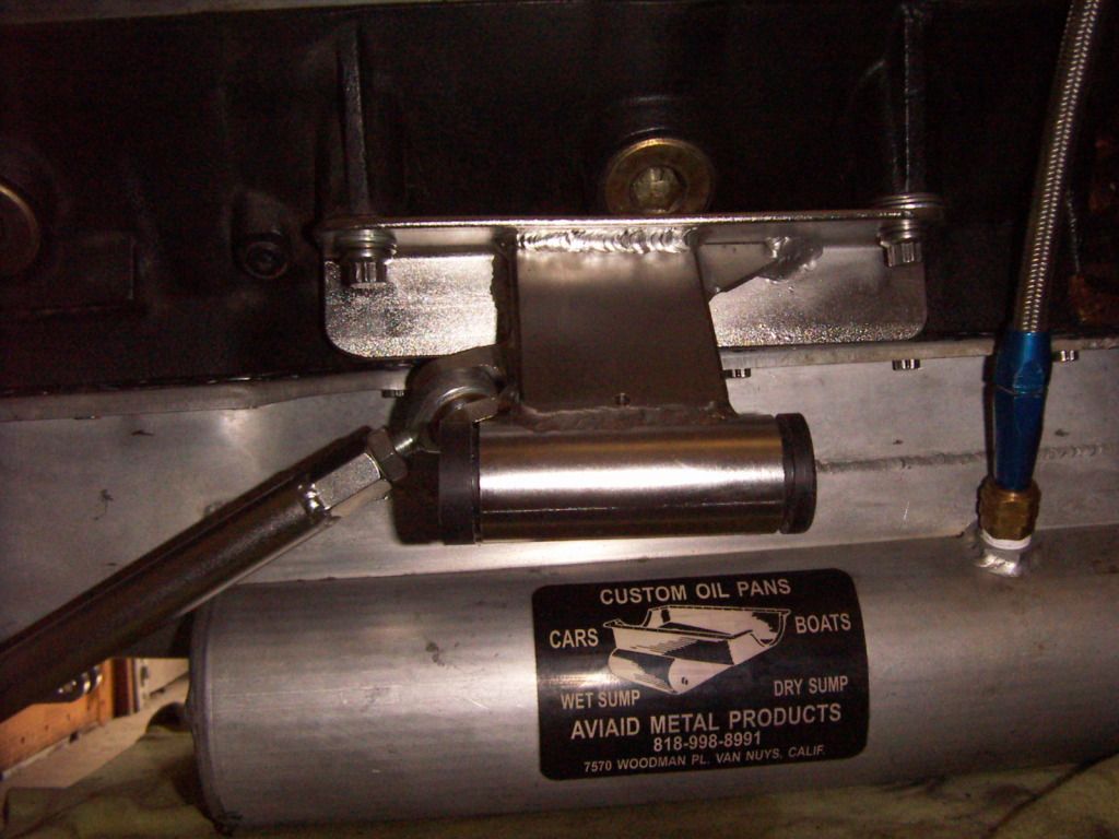
the shims between the engine and the mounts give the engine the correct inclination to fit percectly smooth and without any strees to the long bolts for the adapterplate.
engine is now set at a level which exactly runs parallel to the chassis level.
Adapter plate is also mounted wíth PU bushings.
TOM
I used the usual hard polymounts, but still they allowed the engine to move to much.
I fabed new ones out of angle stock, rectangular tubing and round tubing. ROund tubing filled with Polyurethan bushing and rectangular one equipped with adjustable strut to the adapterplate. Stainless, electropolished.
the shims between the engine and the mounts give the engine the correct inclination to fit percectly smooth and without any strees to the long bolts for the adapterplate.
engine is now set at a level which exactly runs parallel to the chassis level.
Adapter plate is also mounted wíth PU bushings.
TOM
Last edited:
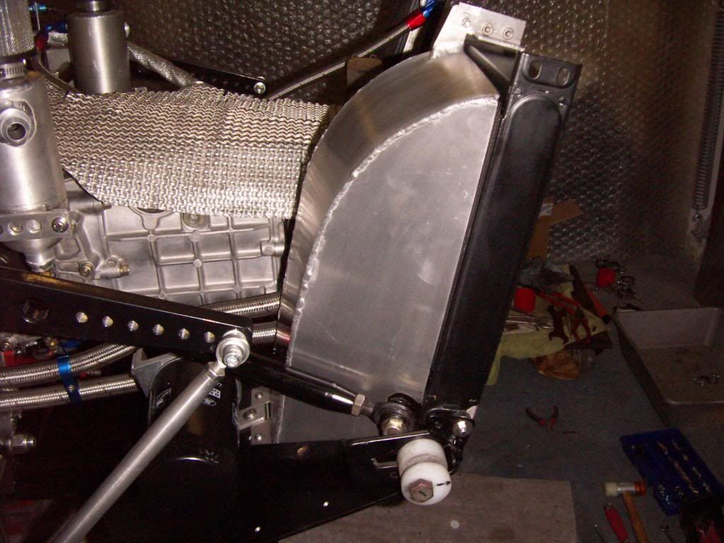
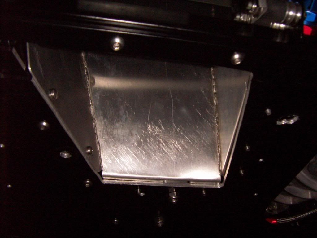
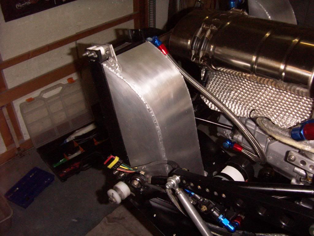

Looking good, Tom! I have a similar idea for mine but more in line with what P1021 has.
GTRene, there probably will be more exposure to road debris but a piece of chicken wire could be used to keep the big stuff out and the reverse airflow ductwork may act as a particle separator (of sorts). It could also be made to open up for track use only.
Here are pics of 1021 at the Shelby Museum in Boulder, CO.
Attachments
Last edited:
Hey Tom
1021 has been what i´m lookng at also. Have tons of pictures of that car from the museum.
I did it a bit wider rather than the taller design 1021 has, due to more road clearance ( the scoop on 1021 looks like it had some ground contact already) of my design. Intake opening area is probably very similar
TOM
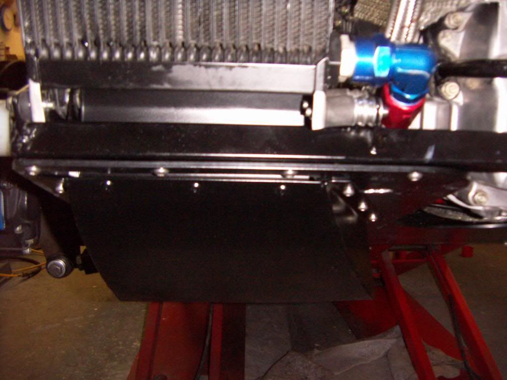
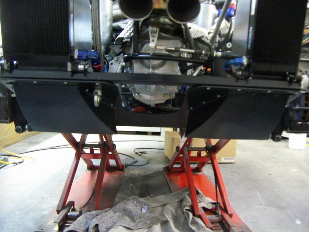
Yes, that fiberglass scoop on 1021 has seen better days....
I'm planning to attach a few strips of yarn underneath and at the rear exit area, and video tape the air flow at different speeds before committing to a scoop design. So this will be something I do after the car is on the road.
Tom
Good idea, let me know your result. The lower scoop is changed quickly to a different design if needed
TOM
- Status
- Not open for further replies.
Similar threads
- Replies
- 46
- Views
- 9K