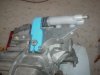
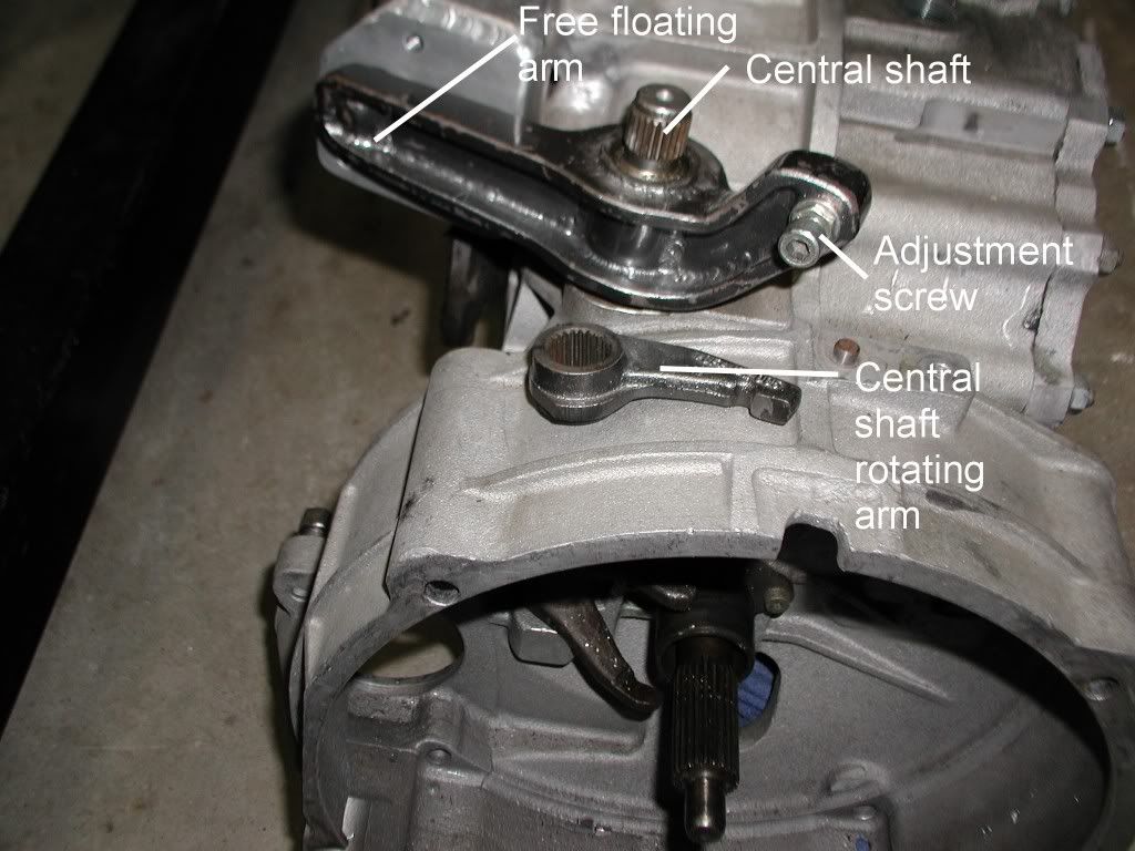
I have a problem with my 930 clutch settings and maybe you guys can help me out. I am trying to set the clutch slave cylinder and pivot bar. For simplicity I have labeled the pivot bar as the long free floating arm, short central shaft rotating arm and central shaft.
The long arm lines up with the slave cylinder housing at 90º without the slave in place. The slave has a throw of 30mm. The shaft of the slave is held in the full open position by an internal spring with a force of 14.4# of pressure.
This force is countered by a balance spring on the opposite side of the long arm.

With no hydraulic fluid in the line and no central shaft rotating arm it holds the long arm at 15mm.In order for the clutch to release the central shaft rotating arm must move 7-8mm. The ratio of the long freee floating arm to the central shaft rotating arm is 2:1. Many of you may remember the Excel spreadsheet that Tom did for the calculations on setting up the clutch mechanism on his G50. They apply for the 930 as well. His reference can be found here: http://www.gt40s.com/forum/gt40-build-logs/13742-drb-5-a-7.html at post 123. .My setup is exactly the same as Tom's. My master cylinder is .75. My master cylinder movement is the same, pedal movement the same and the slave is a standard Porsche with the exception of the internal spring.The pedals are Tilton floor units with a ratio of 5.5:1 in place of the 5:1 that Tom has.
When hydraulic fluid is added, the numbers don't quite add up. With the long free floating arm extended to 30mm and then released to allow it to go to a neutral position(15mm), it stops at 18mm. If the Central shaft rotating arm is placed on the shaft so it can be rotated through its play(wiggled), the arm will go on back to approximately the 15mm mark. If the long arm is compressed into the slave and released it will not go back to the 15mm mark with out wiggling the central shaft.
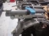
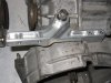
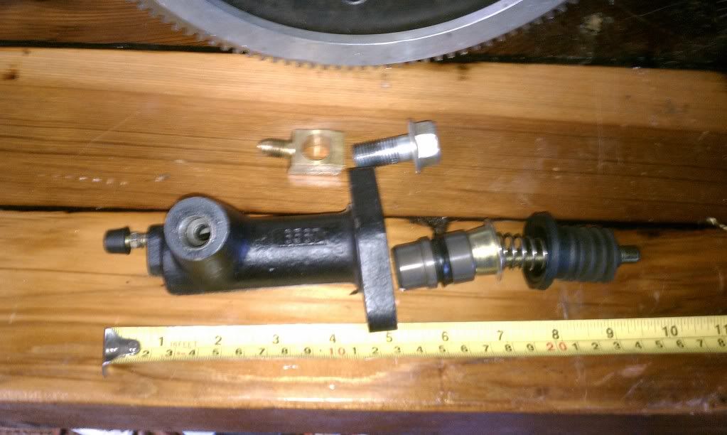
The central shaft has been wiped clean and the long arm shaft has been cleaned and a drop of 90 wgt. transmission fluid applied to give it a slippery surface to slide. Notice the position of the long arm in the following pics.


When all is hooked up the adjustment screw is set. On the 930 it is to be set with 1-2mm of gap between the arms. Sometimes when installing the short central rotating arm a large gap will be present and that screw is to take up that room. The 930s should have no force on the TOB. When put into action, the long free floating arm will not rotate enough for the clutch to release. It seems to go about 10-12mm. Even when there is 0 gap. What this tells me is that the slave is not able to get the long arm to the 30mm mark even though it is at the end of its extension. The only thing that has happened with all this adjusting is that the clutch pedal has developed a zone of free play of one to two inches in its first movement before any resistance is noticed in the pedal. This is with or without any gap of the arms. Sort of like the free play in a mechanical setup. I noticed that the long free floating arm moves about 1 mm and that the fork on the TOB has moved more snuggly against the TOB so that the "ears" of the TOB will not move, whereas they would at the neutral position. This may be nothing?
Here is where the vector stuff comes into play. I need you guys to tell me if it is nothing or something that needs to be worked on or my problem is something else. It is my guess to the problem.
At the first of the post I mentioned the long arm was at 90º to the slave or better to say the slave mounting. When at the 15mm mark the angle is at 78º and at flull extension(30mm) the angle is 68º. The balance spring is not at a true 90º to the short end of the long free floating arm. It is attached to a bolt on the trans adapter that is as close as I could get and it is close to 90º.
I know that there is a lot of physics going on here(Hooks Law, vector/force analysis etc.) so this is where I need some guidance. From what I can figure from the internet, with the angles at less than 90º some of the force exerted in the original direction is lost or rather reduced or redirected and or the distance traveled in the original direction is reduced and the amount of force needed to get to the original point(30mm) is increased. I hope that makes sense. I think what should happen is that the slave needs to be at 90º at the 15mm mark. That way at the 30mm mark the angle will be at 78º and less will be changed. The other idea I have is that the master cylinder needs to be moved in a slight bit to compensate for the reduced travel to get the arm to get to the 30mm mark. I realize this is not a rigid system in that the rod on the slave will rotate some to adapt to the slot in the long free rotating arm, so the angles will be a little off. So if you have an idea chime in, or ask a question
Bill
The long arm lines up with the slave cylinder housing at 90º without the slave in place. The slave has a throw of 30mm. The shaft of the slave is held in the full open position by an internal spring with a force of 14.4# of pressure.
This force is countered by a balance spring on the opposite side of the long arm.
With no hydraulic fluid in the line and no central shaft rotating arm it holds the long arm at 15mm.In order for the clutch to release the central shaft rotating arm must move 7-8mm. The ratio of the long freee floating arm to the central shaft rotating arm is 2:1. Many of you may remember the Excel spreadsheet that Tom did for the calculations on setting up the clutch mechanism on his G50. They apply for the 930 as well. His reference can be found here: http://www.gt40s.com/forum/gt40-build-logs/13742-drb-5-a-7.html at post 123. .My setup is exactly the same as Tom's. My master cylinder is .75. My master cylinder movement is the same, pedal movement the same and the slave is a standard Porsche with the exception of the internal spring.The pedals are Tilton floor units with a ratio of 5.5:1 in place of the 5:1 that Tom has.
When hydraulic fluid is added, the numbers don't quite add up. With the long free floating arm extended to 30mm and then released to allow it to go to a neutral position(15mm), it stops at 18mm. If the Central shaft rotating arm is placed on the shaft so it can be rotated through its play(wiggled), the arm will go on back to approximately the 15mm mark. If the long arm is compressed into the slave and released it will not go back to the 15mm mark with out wiggling the central shaft.
The central shaft has been wiped clean and the long arm shaft has been cleaned and a drop of 90 wgt. transmission fluid applied to give it a slippery surface to slide. Notice the position of the long arm in the following pics.
When all is hooked up the adjustment screw is set. On the 930 it is to be set with 1-2mm of gap between the arms. Sometimes when installing the short central rotating arm a large gap will be present and that screw is to take up that room. The 930s should have no force on the TOB. When put into action, the long free floating arm will not rotate enough for the clutch to release. It seems to go about 10-12mm. Even when there is 0 gap. What this tells me is that the slave is not able to get the long arm to the 30mm mark even though it is at the end of its extension. The only thing that has happened with all this adjusting is that the clutch pedal has developed a zone of free play of one to two inches in its first movement before any resistance is noticed in the pedal. This is with or without any gap of the arms. Sort of like the free play in a mechanical setup. I noticed that the long free floating arm moves about 1 mm and that the fork on the TOB has moved more snuggly against the TOB so that the "ears" of the TOB will not move, whereas they would at the neutral position. This may be nothing?
Here is where the vector stuff comes into play. I need you guys to tell me if it is nothing or something that needs to be worked on or my problem is something else. It is my guess to the problem.
At the first of the post I mentioned the long arm was at 90º to the slave or better to say the slave mounting. When at the 15mm mark the angle is at 78º and at flull extension(30mm) the angle is 68º. The balance spring is not at a true 90º to the short end of the long free floating arm. It is attached to a bolt on the trans adapter that is as close as I could get and it is close to 90º.
I know that there is a lot of physics going on here(Hooks Law, vector/force analysis etc.) so this is where I need some guidance. From what I can figure from the internet, with the angles at less than 90º some of the force exerted in the original direction is lost or rather reduced or redirected and or the distance traveled in the original direction is reduced and the amount of force needed to get to the original point(30mm) is increased. I hope that makes sense. I think what should happen is that the slave needs to be at 90º at the 15mm mark. That way at the 30mm mark the angle will be at 78º and less will be changed. The other idea I have is that the master cylinder needs to be moved in a slight bit to compensate for the reduced travel to get the arm to get to the 30mm mark. I realize this is not a rigid system in that the rod on the slave will rotate some to adapt to the slot in the long free rotating arm, so the angles will be a little off. So if you have an idea chime in, or ask a question
Bill