Due to the recent posts about Waterpump failures i would like to bring in some pump basics.
In my proffessional career i designed a lot of liquid transporting systems with capacities from 2000 l/h to 100000l/h. A lot of them incorporated centrifugal pumps. This is the same working principe as our wp´s.
Generally this pumps are not ment to create high pressure ( max app 8 bar in multistage pumps) and usually not designed for high suction capabilities ( npsh = net positive suction height = app 5 - 6 m in multistage application). To achieve this the pumps need to have a proper impeller and housing design with low tolerances, which is defenitely not the case with our wp´s.
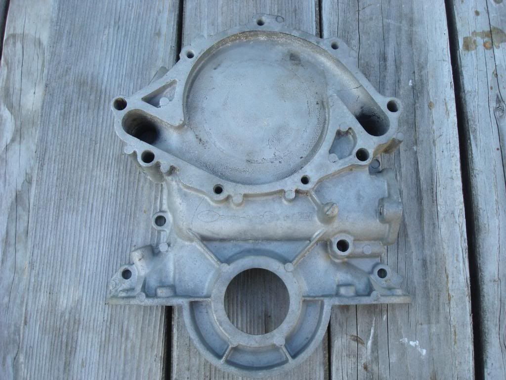
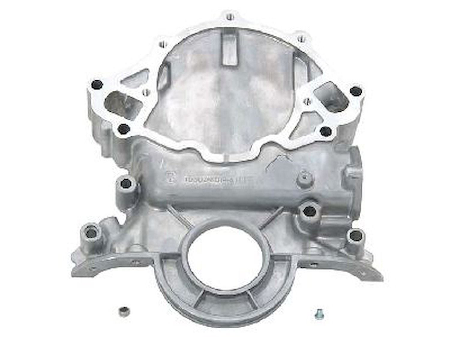
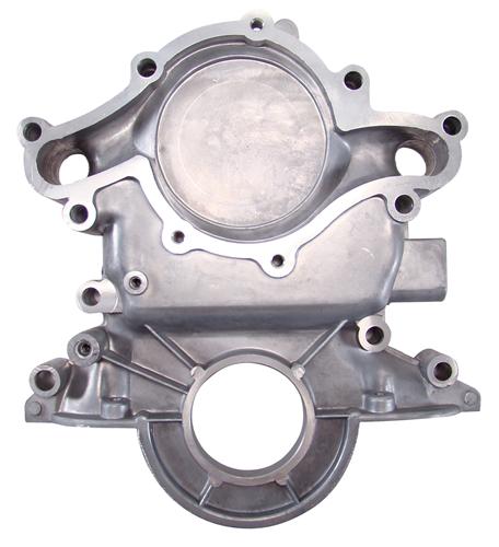
The general working princip: Liquid is entering towards the center of the impeller by the means of the inlet channels

The liquid is than accelerated along the vanes and transported towards the outside of the housing. THis is rather a fan design than a pump design ( like on typical positive displacement pumps, like piston pumps, eaton pumps , membran pumps). The liquid is than transported towards the engine leaving the pumphousing by the two holes in the backplate
Here is a typical graph of an industrial pump

you can see that the Flowrate (MXA) drops pretty quick in relation to the pressuredrop ( pressure resistance). This is a typical property of this pumps. This makes this pumps also very prone to cavitation, because the impeller is still turning at the same speed but the liquid moves less, thus local vacuum spots and steam explosions ( cavitation) can be created.
Our WP´s with the high tolerances from impeller to housing and often poor impeller design will have no suction capabilities at all. So all relies on the pressure capablities which are not high also. This easily explains why wp failures or issues are more frequent on midengine application than on frontengine cars.
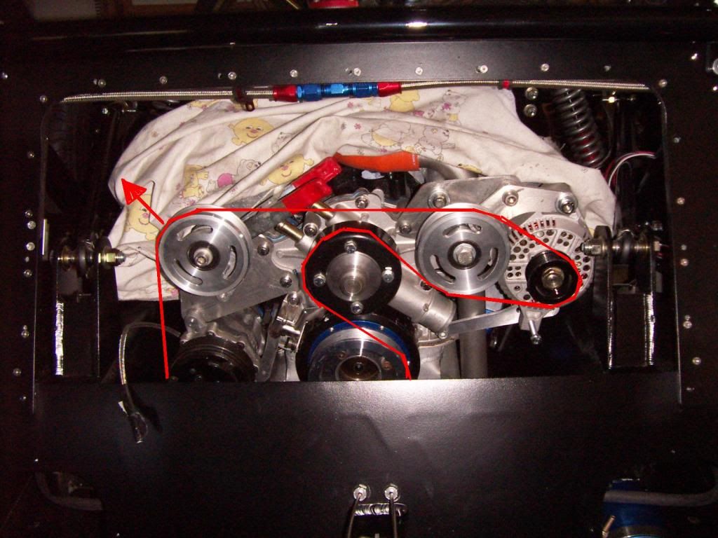
Don´t underestimate the pressuredrop effect in our cars due to the longer pipe length:
This leaves us with the following options:
THanks
TOM
In my proffessional career i designed a lot of liquid transporting systems with capacities from 2000 l/h to 100000l/h. A lot of them incorporated centrifugal pumps. This is the same working principe as our wp´s.
Generally this pumps are not ment to create high pressure ( max app 8 bar in multistage pumps) and usually not designed for high suction capabilities ( npsh = net positive suction height = app 5 - 6 m in multistage application). To achieve this the pumps need to have a proper impeller and housing design with low tolerances, which is defenitely not the case with our wp´s.
The general working princip: Liquid is entering towards the center of the impeller by the means of the inlet channels
The liquid is than accelerated along the vanes and transported towards the outside of the housing. THis is rather a fan design than a pump design ( like on typical positive displacement pumps, like piston pumps, eaton pumps , membran pumps). The liquid is than transported towards the engine leaving the pumphousing by the two holes in the backplate
Here is a typical graph of an industrial pump
you can see that the Flowrate (MXA) drops pretty quick in relation to the pressuredrop ( pressure resistance). This is a typical property of this pumps. This makes this pumps also very prone to cavitation, because the impeller is still turning at the same speed but the liquid moves less, thus local vacuum spots and steam explosions ( cavitation) can be created.
Our WP´s with the high tolerances from impeller to housing and often poor impeller design will have no suction capabilities at all. So all relies on the pressure capablities which are not high also. This easily explains why wp failures or issues are more frequent on midengine application than on frontengine cars.
Don´t underestimate the pressuredrop effect in our cars due to the longer pipe length:
- a typical GT40 system uses around 20 - 24 ft of 1,5" pipe with around 12 to 14 90° elbows. Additionaly it is often a combination of pipes and rubber tubes, with each step adding to the pressure drop. One elbow is an equivalent to 2,5ft of pipe length. this leave us with a total pipelength of around 54 ft. which at a lfowrate of 55 gpm generates a pressuredrop of 5 PSI
- A typical frontengine application uses around 5 - 6 ft of pipe and 4- 5 elbows which adds up to a total pipelength of 16 ft . pressuredrop is 1,5 psi
- if you want to calculate it by yourself Pressure Drop: Calculation of pressure drops in pipes
- this is only the drop generated by the pipes . Add to that the drop of the radiator which will be another 5 PSI .
- in accumulation this can add up to as much as 15 psi. Which is probably already half of our wp´s pressure capability ( i´ve never seen a flowrate vs pressure drop diagram of our wp´s , anyone out there ?)
This leaves us with the following options:
- Optimise piperouting with max diameters and less length and elbows as possible ( for example for front installation use 4 45° elbows instead of 4 90° elbows )
- reducing pressuredrop wherever possible ( wp to engine transferopenings, high flow thermostats, head to intake transferports, block to head transferports)
- high quality high flow radiator
- Looking for high quality pumps with lower tolerances and higher pressure capabilities
- reducing wp speed even further than on a comparable front engine application
- perfect bleeding of the system is a must
THanks
TOM
Last edited: