Remote electric Water pumps / Heater hoses

Randy V

Moderator-Admin
Staff member
Admin
Lifetime Supporter
Does anyone want to share any of their wisdom / pictures in how the connected their heater cores to their cooling system?

In particular - I'm interested in those setups that used remote electric water pumps.

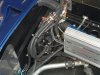
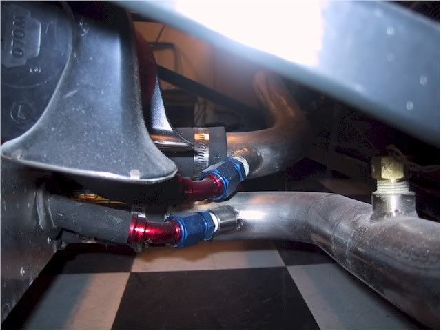
My plan (for now) is to add a draw port to the inlet side of the water pump (mounted just behind the radiator) and a heater feed port to the line (1.5" hose) that carries hot coolant to the radiator.

Please pardon the tape/insulation mockup of major cooling lines. Note - Heater lines not yet in this picture;

IMG_1266.jpg


IMG_1740.jpg
 
Last edited:
Randy,
I have not hooked my heater/AC up yet and don't plan to until the spring. I dug through my old pics and could only come up with the regular hookups like you see below. I think you and I will basicly have the same problem. As I see it, most heater hookups with mechanical water pumps have the hot water going to the unit under positive pressure from the pump and the drain line to the return to the motor, where pressure is less or negative.
Yours and mine will have the positive pressure side returning to the motor and suction from the motor, to the radiator, to the pump. We may have to have ours plumbed backwards where the cooler of the two pipes goes to the heater core and the drain line to the hotter side. Unless you have a small pump that forces flow from the hot side to the cool side I don't think you can get around it. I have not seen the typical temps on the cool side of the radiator, but I would think they would still deliver hot air to the cabin, just not as hot as the standard way. With your climate that might be a marginal amount of heat. Do you know the temps on the cool side??
I think a parallel hookup on the hot side alone wouldn't be very effective(without a pump) as the core would prove to be too high a resistance to flow to be beneficial.
Is that what you were thinking also?

Bill

Heaterplumbing2.jpg


coolantlinesfront.jpg
 

Doug S.

The protoplasm may be 72, but the spirit is 32!
Lifetime Supporter
Not sure if this will help or not, but I remember BillD used a 12V electric pump for an intercooler to push water to his cabin heater.

Doug
 

Mike Trusty

GT40s Supporter
Lifetime Supporter
Randy:

I notice that you are using a bypass thermostat from a '85 BMW 318I. That is a good choice. I have used that one on several cars and there are several people here on the forum that have used it as well. BUT the big question that I have is how in the world did you weld fittings on that thing without bursting the thermostat bulb. You would almost have to destroy it to take it apart because they are rolled together. I sure would like to know your secret.

I'm also a little concerned that you aren't using a pump with two discharges. That would insure that you will get relatively even flow on each side of the motor. It may be difficult to insure that balance with a single pump discharge line extending to the motor.

The way that I suggest providing water to the heater core is a primary/secondary pumping arrangement. Visulize two connections on the return(hot) line from the motor to the radiator that are only a couple inches apart. There are several small pumps available that could then be used to pump water out of that line through the heater core and then directly back into that line. By doing this you are assured that there is no chance of hot water circulating through your heater core due to a faulty or poorly adjusted heater valve. When the pump is off there is no induced pressure to cause the water to go through the core. A pump that I have used many times is the small electric heater pump found in Mercedes cars. They are often easy to find in wrecking yards. If you have to buy one new they are pricey.

I would also recommend that you place your fill tank with pressure cap so that the line from the fill/pressure tank connects to the system at the suction side of the pump. This will set the point of zero pressure change in the system and insure proper operation of pressure cap. This is not as important with a constant flow electric pump as it is with a mechanical pump but still recommended.

The arrangement described above has been done to many exotic cars that I have helped with and at least three GT40's here on the forum. Also used that exact thermostat and piping arrangement that I described on Jack's(2164) Countach with perfect results.
 

Randy V

Moderator-Admin
Staff member
Admin
Lifetime Supporter
As I see it, most heater hookups with mechanical water pumps have the hot water going to the unit under positive pressure from the pump and the drain line to the return to the motor, where pressure is less or negative.
Yours and mine will have the positive pressure side returning to the motor and suction from the motor, to the radiator, to the pump. We may have to have ours plumbed backwards where the cooler of the two pipes goes to the heater core and the drain line to the hotter side. Unless you have a small pump that forces flow from the hot side to the cool side I don't think you can get around it. I have not seen the typical temps on the cool side of the radiator, but I would think they would still deliver hot air to the cabin, just not as hot as the standard way. With your climate that might be a marginal amount of heat. Do you know the temps on the cool side??
I think a parallel hookup on the hot side alone wouldn't be very effective(without a pump) as the core would prove to be too high a resistance to flow to be beneficial.
Is that what you were thinking also?

Bill

Not so sure that my setup will be all that different (operationally) from stock. In regard to pressures, I think the way an OEM heater is connected, the water is sucked from the intake manifold cross-over - through the heater hoses/core, and then to the water pump itself for distribution back into the engine block. I can remember many times where the thermostat would barely open on my cars because I was giving the engine all the cooling it needed simply by running the heater.
Not sure what the "cool" side temps would be coming out of the radiator - but I think they would still be somewhat sufficient for cabin heat.

My plans - right now - are to weld a bung to my Waterpump inlet "Y" pipe. This would be the Suction side of the circuit. Then weld another bung to the inlet side of the T-Stat - this will serve as the hot port that feeds the heater circuit.

Not sure if this will help or not, but I remember BillD used a 12V electric pump for an intercooler to push water to his cabin heater.

Doug

That has some potential too - although I'd like to keep it as simple as possible.


Randy:

I notice that you are using a bypass thermostat from a '85 BMW 318I. That is a good choice. I have used that one on several cars and there are several people here on the forum that have used it as well. BUT the big question that I have is how in the world did you weld fittings on that thing without bursting the thermostat bulb. You would almost have to destroy it to take it apart because they are rolled together. I sure would like to know your secret.

I'm also a little concerned that you aren't using a pump with two discharges. That would insure that you will get relatively even flow on each side of the motor. It may be difficult to insure that balance with a single pump discharge line extending to the motor.

The way that I suggest providing water to the heater core is a primary/secondary pumping arrangement. Visulize two connections on the return(hot) line from the motor to the radiator that are only a couple inches apart. There are several small pumps available that could then be used to pump water out of that line through the heater core and then directly back into that line. By doing this you are assured that there is no chance of hot water circulating through your heater core due to a faulty or poorly adjusted heater valve. When the pump is off there is no induced pressure to cause the water to go through the core. A pump that I have used many times is the small electric heater pump found in Mercedes cars. They are often easy to find in wrecking yards. If you have to buy one new they are pricey.

I would also recommend that you place your fill tank with pressure cap so that the line from the fill/pressure tank connects to the system at the suction side of the pump. This will set the point of zero pressure change in the system and insure proper operation of pressure cap. This is not as important with a constant flow electric pump as it is with a mechanical pump but still recommended.

The arrangement described above has been done to many exotic cars that I have helped with and at least three GT40's here on the forum. Also used that exact thermostat and piping arrangement that I described on Jack's(2164) Countach with perfect results.

Hi Mike - My cousin does a lot a great Stainless Steel and Aluminum fabrication. Shameless plug here ::
http://www.kuhnsautospecialties.com
Mike (my cousin's name) carefully TIG welded the adapters onto the housing. Basically stitching it little by little. He also made the "Y" pipe for me.. My TIG skills are not that good - yet... More practice required! :)

I had planned on having the Coolant reservoir input to the coolant cross-over port on the intake manifold - normally I would go to the water pump (suction). I may have to re-calculate... :blank:

For distribution of coolant back to the engine, I have modified an old water pump (more details on my website) to become a manifold. You can see it in this picture on my mock-up engine.

IMG_1377.jpg
 

Randy V

Moderator-Admin
Staff member
Admin
Lifetime Supporter
Thanks Brett -

Any plans yet for heater hoses / connections and routing?
 
Randy,
I will be taking off the normal heater hose take-offs on the engine. If it doesn't have enough oomph for the heater I will by the small EBP that Davies Craig do and link it to the AC switches.

Routing will go down either of the sills like normal GTDs.

Brett
 

Mike Trusty

GT40s Supporter
Lifetime Supporter
Brett:

From the positioning of the water pump it appears that you are going with a reverse flow through your block. is that correct? This assumption is based on the suction of the electric pump pointing directly at the suction of the mechancial pump housing. I'm also assuming that you have taken the mechanical impeller out of the engine mounted pump housing the same way that Randy has done.
 

Jack Houpe

GT40s Supporter
As per Mike Trusty I used a small Merc Benz electric water pump for my heater core. You must remember to mount the pump below the water line as it will not pump if any air is in the line. My heater core inlet is in the inlet line going to the radiator, about 2 inches downstream I have the outlet.

Randy you will find that pump to be more than enough for you needs, good choice. Its amazing how that system preforms, I have never had my car overheat (engine wise) and ran open road race at 110+ MPH with temps at just at 100 outside.
 
Last edited:
Randy,
I use a Davies Craig EBP that is started via a microswitch on the "heat" slider control inside the car. It is plumbed across the supply and return lines to the radiator. Works well.
Forgive the loose wiring on the stereo. It was being installed when this picture was taken!
Dave
 

Attachments

  • DSCF0088.jpg
    DSCF0088.jpg
    59.9 KB · Views: 467
Back
Top