Stephan's SLC Build Log

Stephan E.

Supporter
From the finished oil cooling system back to the fuel system. The swirl tank was relocated from outboard to inboard. In order to make this accessible, the floor next to the fuel tank received a hatch. Now all fuel components can be reached without any problems from the rear and the bottom.
 

Attachments

  • 20180722_112840.jpg
    20180722_112840.jpg
    506.4 KB · Views: 677
  • 20190112_103039.jpg
    20190112_103039.jpg
    438.9 KB · Views: 681
  • 20190130_151024.jpg
    20190130_151024.jpg
    376.3 KB · Views: 592
  • 20190131_104127.jpg
    20190131_104127.jpg
    315.9 KB · Views: 524
  • 20190201_081818.jpg
    20190201_081818.jpg
    408.3 KB · Views: 590
  • 20190201_081806.jpg
    20190201_081806.jpg
    380 KB · Views: 669
Last edited:

Stephan E.

Supporter
A status update:

The engine bay is 99% done. I made the harness for the accelerator pedal extension and the linkage. Pedal box installed. All fluids are in and the fuel system was primed and adjusted in standalone mode. So far no leaks but I had to rebuild the front brake master cylinder. The one delivered with the kit had a bad seal in it and lost pressure. Found rebuild kit on Ebay. Clutch hydraulics are also filled and bled. I found a suitable crankcase breather, fittings and carbon canister with bracket. Today I ordered my new steering wheel and push button system, more about that when I took delivery. I started routing under dash wiring, closed up the access holes under the dash. Tank cover is installed. Added additional outputs to the rear power cell to drive the door actuators with the key fob. Filler neck is completed. The intake tubes are now all brushed instead of polished. Finished engine wiring and wrapped the exhaust tubes above the V-bands.

Here are some impressions of the finished work
 

Attachments

  • DSC_0226.JPG
    DSC_0226.JPG
    331.9 KB · Views: 439
  • 20190323_184713.jpg
    20190323_184713.jpg
    403.5 KB · Views: 495
  • 20190323_184728.jpg
    20190323_184728.jpg
    476.8 KB · Views: 471
  • 20190323_185025.jpg
    20190323_185025.jpg
    576 KB · Views: 470
  • 20190330_105628.jpg
    20190330_105628.jpg
    454.1 KB · Views: 514
  • 20190330_105853.jpg
    20190330_105853.jpg
    609.7 KB · Views: 555
  • 20190330_105813.jpg
    20190330_105813.jpg
    743.8 KB · Views: 599
  • 20190330_105723.jpg
    20190330_105723.jpg
    770.1 KB · Views: 591
  • 20190324_140108.jpg
    20190324_140108.jpg
    674.9 KB · Views: 569
Last edited:

Joel K

Supporter
Stephan, it’s a work of art how it is all coming together. Love the coolers in the diffuser and many other items. Can’t wait to hear that OHC LS7 come to life!
 

Stephan E.

Supporter
I received the custom made gauges. Though that this is period correct and I just love analog stuff. Everything will sit inside carbon fiber. For now I only have four small gauges for the essential hardware but additional ones already pre-wired. If I can find the space to accommodate them there will be a few more. The two large ones are 4.5 in. OD and some creativity is required to fit them.
 

Attachments

  • 20190301_172226.jpg
    20190301_172226.jpg
    378.1 KB · Views: 574
  • 20190301_172439.jpg
    20190301_172439.jpg
    323.4 KB · Views: 542
  • 20190324_155212.jpg
    20190324_155212.jpg
    447.9 KB · Views: 519
  • 20190218_161638.jpg
    20190218_161638.jpg
    430.2 KB · Views: 459
  • 20190330_154144.jpg
    20190330_154144.jpg
    417.1 KB · Views: 495
  • 20190330_160300.jpg
    20190330_160300.jpg
    458.1 KB · Views: 480

Stephan E.

Supporter
Stephan, it’s a work of art how it is all coming together. Love the coolers in the diffuser and many other items. Can’t wait to hear that OHC LS7 come to life!
Thank you Joel,

It was a rocky road to build this first of a kind engine integration but every time I look at it makes me forget the pain. Startup is not too far...
 

Stephan E.

Supporter
Some progress on the instrument fitment. Took some massaging to get these large roundies where I wanted them. Mockup with acrylic panel so far so good. The final will be in carbon fiber. Molded the perimeter with hairy glass and Bondo for finishing. Now the instrument opening is inverted from what the factory makes. I have to remodel the steering column shroud since all switches will be removed. More to come...
 

Attachments

  • 20190407_132708.jpg
    20190407_132708.jpg
    712.4 KB · Views: 455
  • 20190407_114756.jpg
    20190407_114756.jpg
    424.2 KB · Views: 413
  • 20190407_151353.jpg
    20190407_151353.jpg
    730.8 KB · Views: 387
  • 20190407_153707.jpg
    20190407_153707.jpg
    664 KB · Views: 354
  • 20190412_182713.jpg
    20190412_182713.jpg
    494.8 KB · Views: 334
  • 20190412_182420.jpg
    20190412_182420.jpg
    663.4 KB · Views: 373
  • 20190412_184814.jpg
    20190412_184814.jpg
    454.1 KB · Views: 425
  • 20190412_184552.jpg
    20190412_184552.jpg
    544.4 KB · Views: 465

Stephan E.

Supporter
The other week I ordered the new steering wheel, hub and wireless 8 channel fully programmable push button system. They just came in.
 

Attachments

  • 20190413_074250.jpg
    20190413_074250.jpg
    333.2 KB · Views: 410
  • 20190413_074711.jpg
    20190413_074711.jpg
    271.6 KB · Views: 383
  • 20190413_080312.jpg
    20190413_080312.jpg
    181.2 KB · Views: 445

Stephan E.

Supporter
Here are my continued adventures with my dashboard. I had to modify the steering column, raised it about 3/4" and was able to center it a little better. I have long arms and also noticed that the gauges are covered by the upper part of the steering wheel rim. After the modification I am having an unobstructed view on the instruments and improved ergonomics. I stripped the steering column of all electrical switches, shortened the release lever and modelled a new and much smaller shroud, still being able to adjust the tilt as needed.
 

Attachments

  • 20190427_144628.jpg
    20190427_144628.jpg
    136.7 KB · Views: 425
  • 20190427_145356.jpg
    20190427_145356.jpg
    349 KB · Views: 333
  • 20190427_145410.jpg
    20190427_145410.jpg
    276.7 KB · Views: 435
Last edited:

Stephan E.

Supporter
I was looking around for a while for some nice dash vents and remembered that previous builders used Audi vents. The aluminum trim and the mechanism are second to none. I am finding those aesthetically pleasing and the trim will nicely accompany the rest of the interior but it takes some effort to fit. The pods are at least 1/4" too small because the OD of the vents is the same as that of the pods. There is some modelling required but when in they looking really clean. Here is the left side for now.
 

Attachments

  • 20190427_142735.jpg
    20190427_142735.jpg
    145.4 KB · Views: 354
  • 20190427_142741.jpg
    20190427_142741.jpg
    209.3 KB · Views: 314
  • 20190427_112447.jpg
    20190427_112447.jpg
    568 KB · Views: 324
  • 20190427_114134.jpg
    20190427_114134.jpg
    420.8 KB · Views: 296
  • 20190427_131959.jpg
    20190427_131959.jpg
    391.1 KB · Views: 299
  • 20190427_141432.jpg
    20190427_141432.jpg
    358.1 KB · Views: 332
  • 20190427_141932.jpg
    20190427_141932.jpg
    295.6 KB · Views: 362
  • 20190427_141825.jpg
    20190427_141825.jpg
    301.9 KB · Views: 392
  • 20190427_153943.jpg
    20190427_153943.jpg
    426.1 KB · Views: 389
  • 20190427_112249.jpg
    20190427_112249.jpg
    330.6 KB · Views: 373
Last edited:

Stephan E.

Supporter
….and the passenger side vent. I'll start the center section mockup next.
 

Attachments

  • 20190428_114939.jpg
    20190428_114939.jpg
    258.9 KB · Views: 326
  • 20190428_114952.jpg
    20190428_114952.jpg
    498.4 KB · Views: 381
  • 20190428_115923.jpg
    20190428_115923.jpg
    400.7 KB · Views: 335
  • 20190428_122658.jpg
    20190428_122658.jpg
    408.3 KB · Views: 292
  • 20190428_131143.jpg
    20190428_131143.jpg
    417.7 KB · Views: 351
  • 20190428_152702.jpg
    20190428_152702.jpg
    253.2 KB · Views: 338
  • 20190428_152732.jpg
    20190428_152732.jpg
    313.4 KB · Views: 378
  • 20190428_154457.jpg
    20190428_154457.jpg
    503 KB · Views: 340
  • 20190428_154400.jpg
    20190428_154400.jpg
    525.8 KB · Views: 371

Stephan E.

Supporter
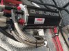
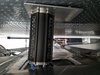
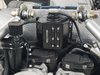
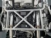
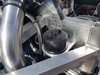
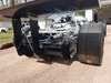
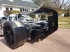
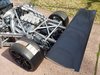
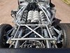
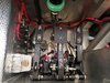
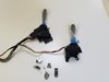
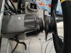
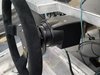
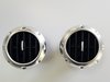
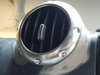
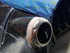
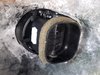
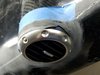
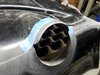
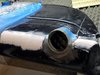
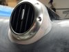
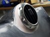
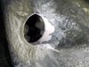
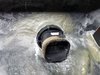
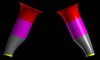
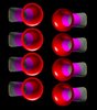
Two month ago I posted success on finishing up my engine bay. Well, that was two month ago. One Sunday morning while happily terminating my dash electrical system and probably drinking too much coffee something hit me. Going back to the beginnings on my build log I was dreaming of using an LS7 with ITBs until the LS7 based Mercury motor became an opportunity with its stock dual throttle body configuration and the ITB idea died. Now over a year later after buying the motor and knowing much more about the engines build quality and its theoretical performance it was time to take the shackles off. I am about to find out what is behind those high airflow values of these cylinder heads. The proprietary wiring and locked ECU was removed including the restrictive intake and the calculations started on a design of a complete new induction system without bottle necks and restraints. The best naturally aspirated design so far is a custom ITB system for these cylinder heads based on tapered 8 x 60mm throttle bodies. A very clean design with the injectors sitting in the heads. Runner length was exactly determined to make max. use of resonating air columns ramming in a lot of fill over standard design manifold hitting that rpm band where the currently installed cams make most power. New intake surface will be almost 100% over the Mercury dual throttle body stock intake. I am still chewing on actuation of the linkage, injector sizes and a matching ECU and harness. Here is the first rendering of the design for calculations and spacing. This is the actual inner surface of the runner length without cylinder heads. The exterior is not considered as of this point. Later it will become a CNC machined billet manifold with flanges for heads and throttle bodies including Carbon velocity stacks. Red are the velocity stacks, purple are the throttle bodies simplified, grey the machined billet manifolds with the transition from longitudinal oval cylinder ports to round 60mm intake ports. Looks like a bottle neck but is just a change in intake runner shape. Yellow is the cylinder head entry.

I can not even imagine how those will sound over 8000 rpm.

Stay tuned...
 

Attachments

  • FRONT_VIEW_INSIDE_SURFACES.JPG
    FRONT_VIEW_INSIDE_SURFACES.JPG
    30.9 KB · Views: 322
  • TOP_VIEW_INSIDE_SURFACES.JPG
    TOP_VIEW_INSIDE_SURFACES.JPG
    33.2 KB · Views: 325
Last edited:

Stephan E.

Supporter
Hello Joel,

that makes two of us. It is a lot right know but I think the outcome will be one of a kind and I have to add drool protection:cool:. Still wondering what that engine will pull when all done.
 

Markus

SPRF40
Lifetime Supporter
Wow!
When I consider your built quality I can't await to see the finished system! The sound I don't even want to think about......

Are you going to use air filters or plenum? Or pure ITB?
Regards
Markus
 

Johan

Supporter
That intake lookes awesome. I have always wondered how you measure total air flow in those. Either if it’s MAF or Speed density, do you measure one stack and program the ECU to multiply by 8 ?
Your build is as usual top notch, very proffesional.
 

Stephan E.

Supporter
Wow!
When I consider your built quality I can't await to see the finished system! The sound I don't even want to think about......

Are you going to use air filters or plenum? Or pure ITB?
Regards
Markus
Hi Marcus,

It all depends on how the package will fit and look when the assembly is completed. I'll make the decision about airboxes along the way.

Stephan
 
Back
Top