Long time coming and lots of thanks to Andrew Jacobson and Brian at Advance Motorsports.
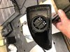
Tried to get this going yesterday. Had a different connector on cam sensor on front of block than the harness. So when I pinned into the correct connector, I reversed power and ground. Could get it to turn over but not fire. Re-pinned this AM and started right up. Then died flat as I forget to plug back in the MAF. Then it fired and ran. Now all the work begins on figuring out how to make the pedal read 0% when not being pushed. Currently reads 29% and goes as far as 84% when all the way to floor. Is this able to be calibrated on a tuner?
Next on the list:
Need to start planning out switches. Need to mount 3 HVAC, ignition key switch, Ram air switch, and a hazard button.
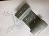
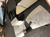
Mount headlights. Got the hella steel plates to solidify mounting structure.
Mirrors?
Run heater ducts and secure bottom side.