
- Forums
- GT40 Replica Manufacturers' Corner
- RCR Forum - RCR40/SLC/917/Superlite Aero
- The SLC Clubhouse
You are using an out of date browser. It may not display this or other websites correctly.
You should upgrade or use an alternative browser.
You should upgrade or use an alternative browser.
Dusty's SLC Build
- Thread starter Dusty
- Start date
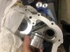
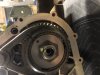
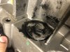
After removing the front wheel drive gears/shaft I had to plug up the hole. At first I bought a cheap set of aluminum seal installation pucks from Harbor freight. I drilled a hole in one of them and tapped an aluminum bolt into the hole. One of the smaller pucks fit well from the backside. This would probably work fine but it wasn’t as good of a solution as the machined parts that Ron makes. So I bought the set from Ron and installed those instead. They are perfect. For what Ron charges just buy his and don’t try to make a set.
Attachments
-
 556A6488-1038-4815-B3A8-0A823156E656.jpeg272.2 KB · Views: 488
 -
 1E689726-1425-465A-8DDB-A0681D81335C.jpeg259.2 KB · Views: 493
 -
 12FFFA66-7A9A-430A-950E-602CB365845D.jpeg364.8 KB · Views: 499
 -
 FB81DF8F-7BFE-4E25-822B-C67D2383F5B6.jpeg410.1 KB · Views: 478
 -
 20943F52-62A8-4C33-A8B5-323ACA9DB1F5.jpeg366.8 KB · Views: 481
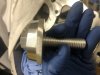
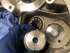
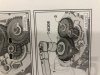
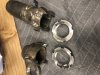
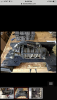
Here is an interesting tidbit for anyone tackling this project. Look at this particular nut in the diagram. Number 15. This nut needs to be whacked with a hammer once it is torqued to help secure it to the shaft. If this nut is removed it Has to be replaced with a new one. There are a total of three such nuts for this project. If you replace the drop gears you will have to replace these three nuts. It would be irresponsible to reuse them. They are distorted once you take them off the shaft. Note that the other two nuts have the same part number but they are not 20mm. I believe they are 27 mm but I’m not sure. The diagram available online has the right nuts.
The problem i encountered is this. There are two separate part numbers for these nuts as shown in the diagram. The diagram represents the nuts in picture I also posted . I originally ordered the 22 mm nut but was a little bummed last night went I went to install the nut and it was the wrong size. I knew the actual size because I had to tap to check it. The size I needed was a 20 mm but when I ordered a nut from a US-based diagram I got a 22 mm part number. I was sent a 22 mm nut based on the diagram I reviewed from a us based deslership. Why are there two different nut sizes? I cannot say. In fact most parts diagrams only reference to 22 mm nut. I goigled this posted diagram showing 2 part numbers by chance. The diagram is in another language and it showed two different nuts. Using the part number on the foreign diagram I was able to order the proper 20 mm nut and it should be here within the next couple of weeks. The sad thing is I waited three weeks to receive the 22 mm Nut from Germany. That nut was $100
The problem i encountered is this. There are two separate part numbers for these nuts as shown in the diagram. The diagram represents the nuts in picture I also posted . I originally ordered the 22 mm nut but was a little bummed last night went I went to install the nut and it was the wrong size. I knew the actual size because I had to tap to check it. The size I needed was a 20 mm but when I ordered a nut from a US-based diagram I got a 22 mm part number. I was sent a 22 mm nut based on the diagram I reviewed from a us based deslership. Why are there two different nut sizes? I cannot say. In fact most parts diagrams only reference to 22 mm nut. I goigled this posted diagram showing 2 part numbers by chance. The diagram is in another language and it showed two different nuts. Using the part number on the foreign diagram I was able to order the proper 20 mm nut and it should be here within the next couple of weeks. The sad thing is I waited three weeks to receive the 22 mm Nut from Germany. That nut was $100
Attachments

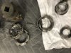
Note that in the picture I posted there are three nuts. The with the yellow mark on it was the original and it is 20 mm. The nuts sitting next to it is the part I ordered which is 22 mm. The nut that is screwed on the shaft is a 20 mm x 1.5 Generic not. If I was lazy I would just use this random nut and torque it.
Johan
Supporter
Welcome to the club Dusty. Everything I need for the car is about 50% more expensive when I get it compared to over there.Here is an interesting tidbit for anyone tackling this project. Look at this particular nut in the diagram. Number 15. This nut needs to be whacked with a hammer once it is torqued to help secure it to the shaft. If this nut is removed it Has to be replaced with a new one. There are a total of three such nuts for this project. If you replace the drop gears you will have to replace these three nuts. It would be irresponsible to reuse them. They are distorted once you take them off the shaft. Note that the other two nuts have the same part number but they are not 20mm. I believe they are 27 mm but I’m not sure. The diagram available online has the right nuts.
The problem i encountered is this. There are two separate part numbers for these nuts as shown in the diagram. The diagram represents the nuts in picture I also posted . I originally ordered the 22 mm nut but was a little bummed last night went I went to install the nut and it was the wrong size. I knew the actual size because I had to tap to check it. The size I needed was a 20 mm but when I ordered a nut from a US-based diagram I got a 22 mm part number. I was sent a 22 mm nut based on the diagram I reviewed from a us based deslership. Why are there two different nut sizes? I cannot say. In fact most parts diagrams only reference to 22 mm nut. I goigled this posted diagram showing 2 part numbers by chance. The diagram is in another language and it showed two different nuts. Using the part number on the foreign diagram I was able to order the proper 20 mm nut and it should be here within the next couple of weeks. The sad thing is I waited three weeks to receive the 22 mm Nut from Germany. That nut was $100
Anyway, I’m doing the drop gear on my KBA tomorrow. Do you have the correct part no for the 3 nuts that’s required?
I would apreciate it very much.

Note that you will need two of these part number seven nuts to complete the install also. 27 mm. No controversy about these particular nuts. Note that if you are reinstalling the front propeller shaft you will need a third one of these 27mm nuts if you want to install the propeller shaft properly. But because I am removing the propeller shaft this nut does not matter Because i am not re-installing it.

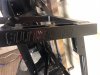
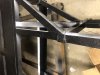
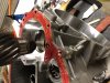
I finished the AC bracket. Turned out pretty nice. Note that I used 3/16 inch chromoly plate. And note that if you build your own like this one you will need three washers as shown in the picture to properly space the AC compressor
Attachments
Johan
Supporter
2 of these
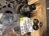
Thanks a lot Dusty.SO JOHAN THSES ARE THE PART NUMBERS
get 2 of part number: 086307303
get 1 of part number: wht002978
So the 086307304 is for the prop shaft or should I order 3 of the 086307303 if reinstalling the propshaft?
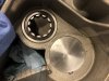
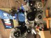
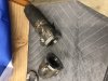
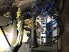
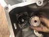
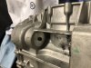
086307303 Is the part number for the prop shaft nut as well as the two nuts your remove Right after you take that black cover off the back of the transfer case. As seen in this pic those are the two nuts on the very end of the input and output shaft. One of them holds on the reverse gear. This part number is the same part number for the nut used to hold on the front propeller shaft nut. 086307303
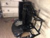
Note that you will need a special tool to remove the pair gear fasteners. And you need a separate tool to hold down the para fasteners that tore the input shaft on. I made these tools myself so that I could properly torque these fasteners once I’m ready to reassemble. Getting them off as easy. You can do that with a modified crescent wrench like I did earlier in the post or with a simple punch and a hammer. But if you want to torque everything back together properly on reassembly You will need a tool.
Ill try and get more pics of the tools I made tonite
Attachments
Johan
Supporter
Here’s another example of what I’m talking about. Note that in this specific diagram Only the 22 mm nut is listed under part 15. Does this have something to do with the V 10 transmission versus the V8 transmission?
Where did you get hold of the catalogue with the part numbers?
there are so many to choose from. simply paste a part number into google and you are off to the races
 www.scuderiacarparts.com

 www.eurospares.co.uk
Lamborghini Gallardo Superleggera Transmission & Pedals | Scuderia Car Parts
Buy original parts for the Lamborghini Gallardo Superleggera Transmission & Pedals. Find your car part today in our extensive catalogue.
www.scuderiacarparts.com
Lamborghini Gallardo Parts | Genuine & OEM Parts
Buy genuine Lamborghini Gallardo parts at Eurospares. View online part diagrams to find all the spare parts and accessories you're looking for!
and to reassemble the case I wouldn't use standard silicone at the auto parts store. you need an anaerobic sealant like this loctite 518. thats whaty i am using. i spent some time searching the factory sealant used by audi and the loctite 518 is equivalent.
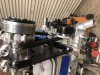
I just welded some 3/16 key stock to some cheap Harbor freight sockets. Looks like I used to 35 mm socket and a 34 mm. Note that the special socket tool that needs to go over the input shaft doesn’t have a deep enough throat so I had to cut the ratchet end off with a chop saw and weld a 30 mm on top of it so that it could Go deeper into the input shaft without bottoming out The tool
Attachments
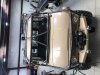
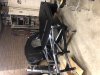
Been doing a lot of work on my unimog to get it ready for The Rubicon in June. Independent pneumatic switch is for all lockers. Front and rear Cages And front and rear hydraulic winch is. Squishy tires are coming. But I did get some work done On the racecar thanks to this great zombie apocalypse
Attachments
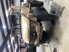
To prep the bottom of the race car I sanded it With an orbital sander and put an etching primer down and then rolled on some hurculiner bedliner. Fully it will quiet down a little bit and help me when I take jumps over speed bumps
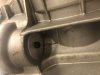
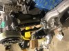
Because I removed the reverse gear I bought one of those nice plugs from Ron to seal up the transmission. The piece from Ron will actually work to keep out dirt and keep the oil in. It is a precision piece.
But for the other hole down stream in the case by the clutch I just used a couple of seal drivers from Harbor freight that were about with the right size. One of them need to be slightly touched with the flapper wheel but they worked well. I drilled a hole in one of them and then I tapped the other and used in aluminum boat from McMaster. I put some RTV sealant on both pieces and tighten them up. I probably could’ve been
Attachments
-
 B7ADE04B-7316-464C-860A-2F6AE374CDC1.jpeg374 KB · Views: 455
 -
 E57FB647-C611-494B-8B12-4D9BC682A778.jpeg988.7 KB · Views: 405
 -
 4E40F3FB-BEDA-4D5D-A4B5-78A396163D71.jpeg413.1 KB · Views: 428
 -
 E28B46AB-9776-44D9-BBA2-CFC0737E7DF7.jpeg289.7 KB · Views: 413
 -
 82C21191-E5B7-4B07-B94D-1AA2C6EB9A96.jpeg507.4 KB · Views: 409
 -
 0737D20E-6C34-4564-8359-FA0564064341.jpeg311.5 KB · Views: 431
 -
 3005052A-3BFC-44CA-9891-987DBE0622F0.jpeg379.2 KB · Views: 444
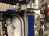
Once the two input/output shafts are assembled in there bearing plate the re assembly is pretty easily accomplished. Another words if you are not doing the sixth gear swap this is not that painful of the job. It’s still something that will likely take you most of the weekend assuming you have the right replacement nuts. I think the sixth gear insulation made things take a lot longer. For me
I use Loctite 518 and after I assembled the bearing plate metal piece to the engine mount peace the whole thing just didn’t feel right. This 518 gasket maker just didn’t seem to be squishing out very well. So I took it apart and tried 515 instead. The 5:15 seem to work much better. My opinion. The only sad part is that after I symbol the case with the 515 I noticed that I had forgot to put the swap gear in the case. So I had to take it all apart again and reassemble it
I use Loctite 518 and after I assembled the bearing plate metal piece to the engine mount peace the whole thing just didn’t feel right. This 518 gasket maker just didn’t seem to be squishing out very well. So I took it apart and tried 515 instead. The 5:15 seem to work much better. My opinion. The only sad part is that after I symbol the case with the 515 I noticed that I had forgot to put the swap gear in the case. So I had to take it all apart again and reassemble it
Attachments

Similar threads
- Replies
- 36
- Views
- 8K
- Replies
- 26
- Views
- 8K
- Replies
- 7
- Views
- 6K
- Replies
- 64
- Views
- 17K