
- Forums
- GT40 Replica Manufacturers' Corner
- RCR Forum - RCR40/SLC/917/Superlite Aero
- The SLC Clubhouse
You are using an out of date browser. It may not display this or other websites correctly.
You should upgrade or use an alternative browser.
You should upgrade or use an alternative browser.
Stephan's SLC Build Log

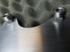
NICE WELDING !!!!!
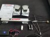
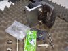
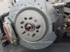
My Tesla Calipers arrived the other day and I went over to see Jon Haas at Pantera Electronics in Harleysville PA. Lucky me it was only a few towns over and Jon gave me a tour to see his wonderful original 1972 white Pantera. I picked my cable, connectors and push button controller while being over there. Jon, an electronic engineer and enthusiast to develop electrical and electronic components to make older cars more reliable. He has some really cool stuff and a ton of ideas for the future.
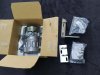
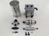
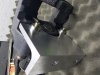
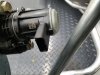
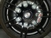
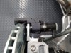
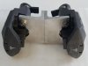
Here is my SLC version with Tesla calipers. I machined the brackets from 6061-T6, used stainless, serrated and threaded push in bushings. Bolts are M10 x 1.5 x 90mm 10.9 flanged. The unthreaded area of the bolt is just long enough that the caliper sliding sleeves are not hitting any threaded area. I raised the calipers slightly to make room for the push rod from the lower control arms. I was able to use the old attachment points of the previous calipers without any changes.
Here is my SLC version with Tesla calipers. I machined the brackets from 6061-T6, used stainless, serrated and threaded push in bushings. Bolts are M10 x 1.5 x 90mm 10.9 flanged. The unthreaded area of the bolt is just long enough that the caliper sliding sleeves are not hitting any threaded area. I raised the calipers slightly to make room for the push rod from the lower control arms. I was able to use the old attachment points of the previous calipers without any changes.
Attachments
-
 20200503_185027.jpg269.2 KB · Views: 633
 -
 20200503_170643.jpg354.2 KB · Views: 583
 -
 20200503_154450.jpg745.8 KB · Views: 631
 -
 20200503_154620.jpg478.1 KB · Views: 615
 -
 20200503_183211.jpg292.7 KB · Views: 646
 -
 20200502_201419.jpg378.3 KB · Views: 661
 -
 20200503_183607.jpg467.4 KB · Views: 588
 -
 20200503_183223.jpg317.1 KB · Views: 626
 -
 20200503_181439.jpg247.7 KB · Views: 726
Last edited:
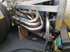
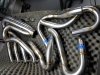
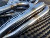
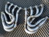
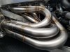
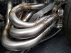
New Exhaust System Rev.1, Chapter 6 and final chapter for the headers.
The headers are finished and I installed them this evening. I had some concerns about heat deformation with all the welds but it turned out that they fit like a champ. Collectors mated to the rear system and manifolds to the heads without any stress or force. Distances and spaces could be maintained as laid out. The recap of this little DIY project is that I would always do it again. I am sure it was a lengthy story but I hope it was enjoyable. Still some hangers and brackets required and the exhaust tips are on the drawing board...
The headers are finished and I installed them this evening. I had some concerns about heat deformation with all the welds but it turned out that they fit like a champ. Collectors mated to the rear system and manifolds to the heads without any stress or force. Distances and spaces could be maintained as laid out. The recap of this little DIY project is that I would always do it again. I am sure it was a lengthy story but I hope it was enjoyable. Still some hangers and brackets required and the exhaust tips are on the drawing board...
Attachments
Johan
Supporter
Looks very professional Stephan. Just make sure the connection between the 4 pipes and the collector is sealed/tight, or you will have false readings from the O2 sensors.New Exhaust System Rev.1, Chapter 6 and final chapter for the headers.
The headers are finished and I installed them this evening. I had some concerns about heat deformation with all the welds but it turned out that they fit like a champ. Collectors mated to the rear system and manifolds to the heads without any stress or force. Distances and spaces could be maintained as laid out. The recap of this little DIY project is that I would always do it again. I am sure it was a lengthy story but I hope it was enjoyable. Still some hangers and brackets required and the exhaust tips are on the drawing board...
Hello Johan,Looks very professional Stephan. Just make sure the connection between the 4 pipes and the collector is sealed/tight, or you will have false readings from the O2 sensors.
Good point and it hit me early in the layout of the system. Usually headers are being build from the manifolds backwards with the tubes meeting at a certain point to enter a collector. This can carry the risk that if the collectors are not equal or precise enough the inserted tubes will to meet the end of the sleeves. That situation could be a reason for a leak. I had to build my system from the back forward. The collectors are symmetrically positioned on either side of the car and the headers are unsymmetrical but still equal in length. To eliminate tolerance from the collector sleeves, I inserted stubs and moved towards the manifolds. The stubs should be in full contact with the sleeves end where it decreases its ID at any given time. This decision created a lot of more work because if the headers would be symmetrical it would have been easier and less time consuming. It will also require never to change the collector orientation but that is an easy thing to control. Due to offset of the cylinder banks some radii are different to make up for it. Still, was a lot of fun to make.
Cheers
Last edited:
Hello Ben,
Yes I did. Looked really nice on the inside too. Somewhat very sanitary")
Yes I did. Looked really nice on the inside too. Somewhat very sanitary
I wanted to share this alternate approach of fitting an SB4 engine into a SLC chassis. Here it is done on a Falcon F7 which is using an SLC base and wearing a different dress over it.This owner decided to go with water pump and accessory drive in place and had to cut and weld the living daylight out of that poor car. Also this car is not for the faint hearted. It has received Garrett twin turbos on top of the 750 stock ponies, Holley ECU, lower compression pistons.... New output, "Astronomical units"
Is there a link to that Falcon build? I cant find it.
My Tesla Calipers arrived the other day and I went over to see Jon Haas at Pantera Electronics in Harleysville PA. Lucky me it was only a few towns over and Jon gave me a tour to see his wonderful original 1972 white Pantera. I picked my cable, connectors and push button controller while being over there. Jon, an electronic engineer and enthusiast to develop electrical and electronic components to make older cars more reliable. He has some really cool stuff and a ton of ideas for the future.
Here is my SLC version with Tesla calipers. I machined the brackets from 6061-T6, used stainless, serrated and threaded push in bushings. Bolts are M10 x 1.5 x 90mm 10.9 flanged. The unthreaded area of the bolt is just long enough that the caliper sliding sleeves are not hitting any threaded area. I raised the calipers slightly to make room for the push rod from the lower control arms. I was able to use the old attachment points of the previous calipers without any changes.
Hello Stephan, I am interested in replicating your Aluminum mounts. Can you provide the thickness of the angle aluminum and some dimensions? Also, will you share part numbers for the push-in bushings?
Hello Mason,
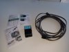
The serrated push in bushings are available from IPSCO which makes the cable pull version of the calipers that came with my kit.
Mark Johnson at IPSCO will sell them individually for about $3.00. I spent $28.00 for 8 including shipping. His number
303-252-4481 and email [email protected]. These inserts are available in 3/8" and in M10.
The angle aluminum is from Mcmaster Carr. Its T6061-T6 3/8" thick in 6" x 4" with rounded inner edge. I needed 12" to make both brackets.
Part Number https://www.mcmaster.com/8982K95
Have fun making those brackets.
Last edited:
Hello Mason,Stephan, why did you need 8 push-in bushings? I'm only seeing 4 being used between the two calipers.
The extras were purchased just in case I have another application that requires high torque and has no room for a nut or enough room to get a wrench on.
Cheers
Can you make me a mold of those Headers and pipes?New Exhaust System Rev.1, Chapter 6 and final chapter for the headers.
The headers are finished and I installed them this evening. I had some concerns about heat deformation with all the welds but it turned out that they fit like a champ. Collectors mated to the rear system and manifolds to the heads without any stress or force. Distances and spaces could be maintained as laid out. The recap of this little DIY project is that I would always do it again. I am sure it was a lengthy story but I hope it was enjoyable. Still some hangers and brackets required and the exhaust tips are on the drawing board...
Hello Aaron,
Just get the ICengineworks header kit for the OD of your header tubing and you will be good to go. Very intuitive tool, highly recommended and it worked great for me.
Just get the ICengineworks header kit for the OD of your header tubing and you will be good to go. Very intuitive tool, highly recommended and it worked great for me.
Thank you Stephan.Hello Aaron,
Just get the ICengineworks header kit for the OD of your header tubing and you will be good to go. Very intuitive tool, highly recommended and it worked great for me.
Similar threads
- Replies
- 19
- Views
- 4K
- Replies
- 8
- Views
- 4K