
You are using an out of date browser. It may not display this or other websites correctly.
You should upgrade or use an alternative browser.
You should upgrade or use an alternative browser.
917 Scratch Build
- Thread starter MrNoo
- Start date
Hi all,
Thought I`d do an update as not posted in a while. Goyt all the chassis TIG welded up, very pleased with it. I have made a new front body section, glass and carbon, a lot lighter this time, first pic is of it being trial fitted to our CAD chassis
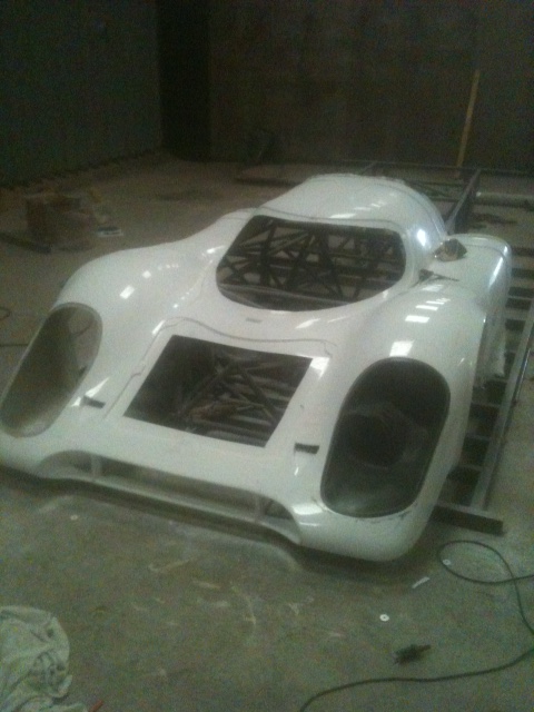
I then set about rough trimming it and fitting the sills to see how it all fitted together on the CAD chassis (turns out that the chassis is 4mm narrower that my original, but it all fits a treat!)
Anyway a picture of it together
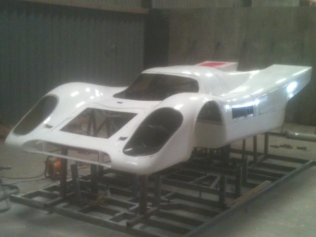
And then one of the side support for the body plus fuel filler assembly, fits ok
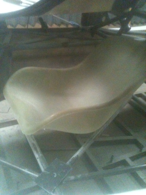
Then I moved onto the seats, managed to get a seat back from a chap who races Formula Fords, took a mould and did some seats, only problem is that after doing all this I could not fit comfortably in the ruddy thing!!! So back to the drawing board, I have trimmed the front of the seat down, so at least I now fit ok in it, just need to tidy it up and put some flanges on and do another mould!
Pic of original seat in place. Not a great picture I`m afraid!!
And that's where it at so far, will hopefully have the seats all sorted in the next week or 2!!!
regards C
Thought I`d do an update as not posted in a while. Goyt all the chassis TIG welded up, very pleased with it. I have made a new front body section, glass and carbon, a lot lighter this time, first pic is of it being trial fitted to our CAD chassis
I then set about rough trimming it and fitting the sills to see how it all fitted together on the CAD chassis (turns out that the chassis is 4mm narrower that my original, but it all fits a treat!)
Anyway a picture of it together
And then one of the side support for the body plus fuel filler assembly, fits ok
Then I moved onto the seats, managed to get a seat back from a chap who races Formula Fords, took a mould and did some seats, only problem is that after doing all this I could not fit comfortably in the ruddy thing!!! So back to the drawing board, I have trimmed the front of the seat down, so at least I now fit ok in it, just need to tidy it up and put some flanges on and do another mould!
Pic of original seat in place. Not a great picture I`m afraid!!
And that's where it at so far, will hopefully have the seats all sorted in the next week or 2!!!
regards C
Nice job Chris...Its a whole lot more work than most people realise... many of us do know though.
BTW ...I saw your post on another forum and I totally agree 100%
BTW ...I saw your post on another forum and I totally agree 100%
Last edited:
Nice job Chris...Its a whole lot more work than most people realise... many of us though.
BTW ...I saw your post on another forum and I totally agree 100%
Thanks Fran, a lot of work but I love it!!!
Mic, that pic is of the seat as it was, I could fit very nicely in the seat but in the car there was no room for my head!! (sometimes being tall is a pain!!!) So I have taken circa 6 inches off the front of the seat to enable a more reclined position to be had, will also try and get the sides of the seat parallel to the sill tops, looks smarter!
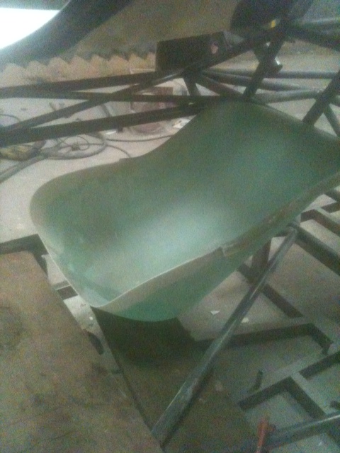
A pic of the loosely trimmed seat, In this position I fit fine, even have a little headroom! Still have some playing around to do with it to get it exactly how I want it
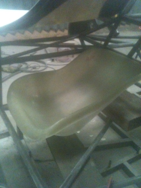
Got the seat saga sorted now, pic of first one out the 2nd mould and placed in position, only another 5 to make! I guess there could be a "spot the difference comp!"
Very nice Chris! :thumbsup:
Looks a bit deeper and I like the rolled edges!
Cheers Randy, no not deeper, around 6" shorter so is in fact shallower!!! Edges are just loosely trimmed, bit more to come off them yet.
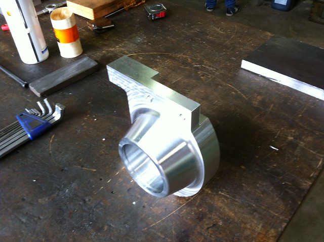
Eve all, harvest done just some drilling to do then car work beckons!! Have our first upright machined, just got to trial fit all the parts, we have a front and rear done, we need to check they are all ok then we`ll be getting a couple of sets done, these include steering arms and top rose joint mounts. So some progress and hopefully much more to come over the following 4-5 months for you all!!
Maybe I missed it but why did you scratch your first chassis and start over with a CAD chassis?
Maybe I missed it but why did you scratch your first chassis and start over with a CAD chassis?
For a whole host of reasons!
I was just going to build one for myself, hence the first chassis. CAD chassis is more accurate than I could do myself and also having done a first chassis (mock) it gives me a good idea where everything fits etc and any changes that need to be made. Also doing it in CAD enables more than one to be constructed and alterations to be made very quickly if needed. Also making fiberglass parts for the chassis, I know that if a certain part fits my chassis it will also fit exactly other chassis. We are finding this with parts made from my chassis fitting exactly on Marcel`s chassis over in Holland.
Also I want things to be perfect, so in using CAD I feel the chassis is straighter, stronger and generally more accurate all round. It is also a lot quicker to assemble (esp using a CAD designed jig) eg CAD chassis took a day and a half to tack weld and then a week to weld up (TIG) where as my old school chassis took 7 months of work!!!!
All the CAD stuff was done by Marcel ( I don`t have a clue, instead prefer to see things with my eyes, bit of a "chalk on the floor type") but the benefits of CAD are easily seen in the finished article.
Hello Chris
Did you go forward on your own project ?
some pics of new things coming ???
Can wait to watch more ! LOL
Hi Mic,
Trust you are keeping well? Will be back on it shortly, have a week`s holiday soon then back on the car, so progress reports will be forthcoming soon!
How`s yours doing? Must be nearly done?
regards Chris
Hello
Yes post more please ! I really enjoy each time you show us some progress
I am doing all the small accessories and ducts to bond to the main bodywork as it is now fully laminated to the chassis
And also I spend 2 weeks in trying to find the right cinematic to open the doors and then cut this very very specific hinges !!!!!!!!!!!!!!!!
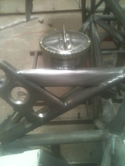
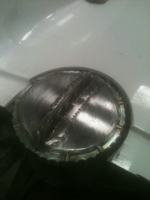
Getting back into it now! Have done the fuel tank, I have used th original Cayman S pump but in my own collector (parts should be available anywhere if needed) I used 3mm alloy, a couple of baffles and a crafty one way valve (just took the one out the original Porsche pump) that is just a rubber bung with 5 holes under it, hence will permit flow one way and not t'other.
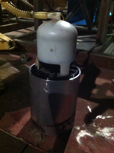
This collector tube is welded to the bottom of the tank.
I then set about welding up the tank, done the mounting plates today, will have a look at the mounting straps tomorrow.
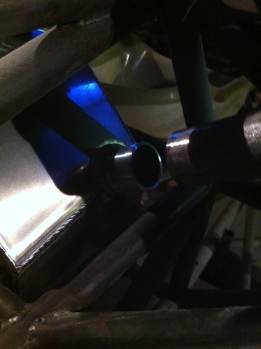
Am very happy with it, just hope it all works, still have the plate to make for the breather/fuel feed/level sensor, drill and tap the holes and it'll be done.
regards C
This collector tube is welded to the bottom of the tank.
I then set about welding up the tank, done the mounting plates today, will have a look at the mounting straps tomorrow.
Am very happy with it, just hope it all works, still have the plate to make for the breather/fuel feed/level sensor, drill and tap the holes and it'll be done.
regards C
Eve all,
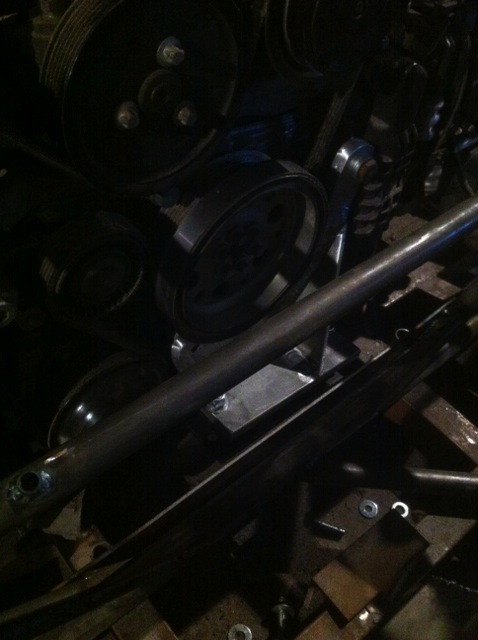
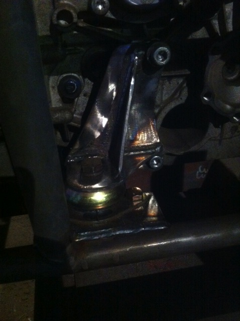
Been getting on with it, managed to get the engine mounted, went for rubber mounts, 2 failsafe's at the rear and a large sandwich mount at the front (rated at 1000kg) only 7inches long and 3 wide.
Anyway pic of front mount (bit dark I'm afraid) made a 1/2 alloy front plate and welded another in a horizontal plane to sit atop the sandwich mount.
 Second one is of the rear failsafe mount on transaxle
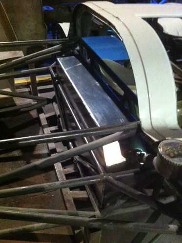
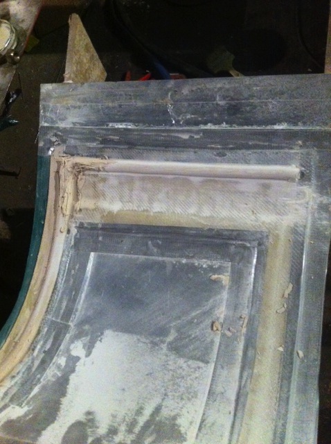
And have now started doing the inner door skin strengthening rib, I hope to bond this to the outer and when doing so sandwich in the door hinge mounts too, do two jobs in one operation hopefully, will see how it pans out. Pic of the filler rib being made, I will then take a mold off this, will need to make a jig for hinge location points.
regards Chris
Been getting on with it, managed to get the engine mounted, went for rubber mounts, 2 failsafe's at the rear and a large sandwich mount at the front (rated at 1000kg) only 7inches long and 3 wide.
Anyway pic of front mount (bit dark I'm afraid) made a 1/2 alloy front plate and welded another in a horizontal plane to sit atop the sandwich mount.
And have now started doing the inner door skin strengthening rib, I hope to bond this to the outer and when doing so sandwich in the door hinge mounts too, do two jobs in one operation hopefully, will see how it pans out. Pic of the filler rib being made, I will then take a mold off this, will need to make a jig for hinge location points.
regards Chris
Chris,
good work as usual, but am surprised you are not making your door stiffening "frame" from metal tubing with your hinges welded to it, as well as the door lock. The nature of the 917s doors makes them very vunerable to weather-human-unforeseen "abuse".
I know you are doing your own thing and not following originality, but the doors can be a right pain for keeping "tight" so to speak, and with you wanting to put it to road use I can,t help thinking that just GRP ribbing will not really be sufficient, especially when pushed against rubber weather sealing strip or tubing.
Good work though.
Similar threads
- Replies
- 13
- Views
- 3K
- Replies
- 5
- Views
- 2K
- Replies
- 14
- Views
- 5K