A Riviera scratchbuilt GT40

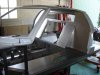
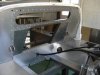
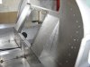
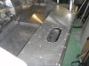
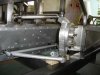
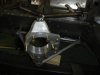
These last weeks, I focused the build on the uprights and suspension parts, as I received the lathe mill combo which I ordered in China 4 months ago...
My objective was to have a, in house, compact, versatile machine, with an attractive lathe axis-to bed distance : 210 mm.
I use it mainly on aluminum alloy machining, but it can also work on steel with very acceptable precision, until you accept to work very slowly....

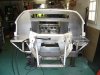
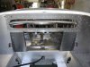
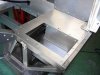
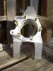
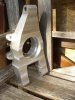
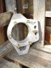
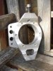
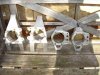
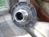
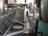
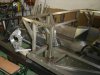
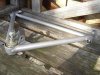
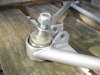
The uprights are alloy made, 3 parts each and wheel hubs are based on AUDI hubs and bearings :

Rear : 82 mm OD , 37 mm wide
Front : 75 mm OD, 37 mm wide

The corresponding wheel hubs are from AUDI 100 ( same on A 6)and AUDI A 4 ; easy to find in France in junkyards ; from 10 to 20 € each ...

The uprights are Al/Zn ( 7075) for front and Al/Cu ( 2017A) for rear.

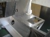
I worked from the design we made with my mate Christian ( Solidworks expert...)
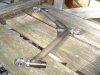
The rought shape was made from alloy blocks with ribbon saw, and then precision finished on the lathe and the mill ( flycutter)
 

Attachments

  • gt40 049 upright.jpg
    gt40 049 upright.jpg
    30.1 KB · Views: 1,849
  • gt40 050 upright.jpg
    gt40 050 upright.jpg
    30 KB · Views: 1,721
  • gt40 051 upright.jpg
    gt40 051 upright.jpg
    33 KB · Views: 1,551
  • gt40 052 upright.jpg
    gt40 052 upright.jpg
    31.4 KB · Views: 1,631
  • gt40 053 upright.jpg
    gt40 053 upright.jpg
    54.9 KB · Views: 1,864
  • gt40 074 wheel hub.jpg
    gt40 074 wheel hub.jpg
    46.9 KB · Views: 1,743
I attach some drawings : pdf

The original drawings are exploitable from Edrawing ( To get on the Web), but apparently they are not accepted from the forum software...

If any of you has a solution, I will be happy to test it ...
 

Attachments

  • Upright rear assy.pdf
    25.7 KB · Views: 2,479
  • Upright front assy.pdf
    33.7 KB · Views: 1,882
  • Upright rear drawing.pdf
    32.4 KB · Views: 1,974
NIce job Rene

but it looks like you made two "lefts" for the front ?

Also why did you do a 6 hole PCD when the bearing hub shown is a 5 hole ?

TOM
 
Thank you Randy ; now the next step is to check if the parts do the job they where designed for!

Tom, well seen... In fact the front upright are 2 axis ( Vertical, horizontal) symetrical, and I did not paid attention when doing the picture that I made the dummy assembly in the same way....

About the 6 bolts , those you see are dedicated to the upright 3 parts assembly : Main body, caliper holder , and bearing holder ( Not yet machined).

The hub 5 holes are the standard Audi 112 mm PCD

I still wonder if I go to "wrong" 5 studs wheels ( Ie Team III Halibrand) or to a real knock -off solution with adapters to bolt on the AUDI hub ...

Question of cost and weight versus keeping close to the legend!

I would be happy to get advices and experience on the subject
 
By the time we designed the uprights, I fixed the suspensions main features and started the build up on the main following solutions

*Paralell A arms with no anti-dive angles : after investigations, it seems that a good anti-dive system needs important angles ( As designed on some Corvette) to be effective and I was reluctant to include the modifications on the chassis design ....

*All arms to chassis connexions are rod end equiped , from MC GILL MOTORSPORT ( Good price, good service ), 1/2 " and 5/8 " size;

*The arms are chromoly steel ( 25CD4S - 4130) made - 25x2 mm, and 20x1.5 mm, with MIDWEST CONTROL chromoly end bungs .

*The front lower ball joints are MOOG parts. (From Mercedes SL 500 ; they should do the job !) - Upper are 5/8 " size rod ends.

*As coating, I decided to go to a standard epoxy powder, and I avoided the chrome solution which is supposed to create problems at the welded places ....

I presently made a dummy assembly of the front suspensions (pictures) and plan to make is soon for rear ...
 

Attachments

  • gt40 064 Suspension.jpg
    gt40 064 Suspension.jpg
    40.7 KB · Views: 2,335
  • gt40 065 suspension.jpg
    gt40 065 suspension.jpg
    25.8 KB · Views: 1,915
  • gt40 066 suspension.jpg
    gt40 066 suspension.jpg
    39.8 KB · Views: 2,506
  • gt40 069 chassis suspension .jpg
    gt40 069 chassis suspension .jpg
    44.6 KB · Views: 2,773
As new chapter , Glen, I can post now the main drawings I made for the chassis build ;

They where designed "from scratch", but I took ideas from several sources:
Pictures, kit builders , historic GT40 , Webguy drawings etc ...

They where first made on table with pencil, and then converted to Solidworks; the version which I post are pdf scans of printed versions in ordre to get easy access.

I cannot confirm at this time that they are correct for building a fully "road compatible " car ...but all the verifications and controls I made till now are in the right direction .

My chassis is stainless steel made, but there is obviously no problem to go to mild steel for easier assembly and welding.

The main point is to add some diagonal stiffening rails ( see previous pictures) in the critical areas .

I made some torsionnal stiffness monitoring , from the very beguining and I now have to do new measures to see the (supposed...) improvement ; I will post on the results when made.
 

Attachments

  • Chassis drawing 1 level .pdf
    29.7 KB · Views: 3,068
  • Chassis drawing 2 level view.pdf
    44.6 KB · Views: 2,372
  • Chassis drawing - 0 level .pdf
    37.5 KB · Views: 2,152
  • Chassis drawing front view.pdf
    75.1 KB · Views: 2,048
  • Chassis drawing lateral view.pdf
    36.5 KB · Views: 2,015
  • Chassis drawing perspective view .pdf
    49.5 KB · Views: 2,123
  • Chassis drawing rear view.pdf
    47.7 KB · Views: 1,930
  • Chassis drawing top view.pdf
    39 KB · Views: 2,157

Randy V

Moderator-Admin
Staff member
Admin
Lifetime Supporter
You put in a LOT of work into those Rene! Good job!!! :thumbsup:
 
Thanks Randy , for the encouragements ...

The fact is that I first spent a lot of time on the project preparation, forums reading ( GT40s.com on top of them of course..) technical informations analysis etc ...and when we started the SOLIDWORKS drawings with my friend Christian, I felt quite "confortable" ( sic ...) on the decisions to be taken at each step .

The design itself took approx 10 working ( holidays !) days , which is not so long ...

And at the present build up step, all this reflexion time is an asset to choose the best solution at the right time .(Nevertheless , I made some mistakes , and I expect to discover others in the future...)
 
Nice work Rene
I specialy like the craftmanship in the shifter mechanism. is it your own design.
Keep up the good work.
Woody
 
I am happy you appreciate the work Woody...

The shifter mecanism is my design, but not my idea !
It comes from gathering several ideas in this forum and designing with objective to be : efficient , compact and as simple as possible to install and to maintien ...

From the first static tests I made, it works properly and the disconnexion/connexion from/to the box needs 3/4 mn .

Now, the point is to test in dynamic situation and also to check accessibility and heat behaviour when the engine exhaust will be installed closely ...

I attach the draft drawing I made for the construction, on the G50 J03 I have .

Do you plan to modify the shifter system on your DRB ?
 

Attachments

  • G50 shifter .pdf
    59.4 KB · Views: 1,844
Rene
I have a G96 trans and this uses two cables but the DRB system for the G50 could be made simpler with your system.
I like your workmanship and will keep a close eye on your build
Woody
 
These last weeks,I worked mainly on the rear bulkhead which I had left non welded until the floor pan was achieved .

By the same time, I achieved the top sills pannelling , with the same aluminum 6082 than floor pan ; I made access traps for the fuel cans, despite I do not exactly know at this time what kind of stuff I will install as fuel sender, fuel pick up, return, etc ...

The other point which I left "open" is the isolation issue in the core bulkhead; my plan was to inject poluyrethane foam in the available space ( 40 mm wide) between the aluminum sheets, but I am a little bit anxious on the warpage risk ...

So, I left it for an another day...Any advice or experience feed-back will be welcome ...
 

Attachments

  • gt40 076 bulkhead.jpg
    gt40 076 bulkhead.jpg
    68.8 KB · Views: 1,958
  • gt40 077 bulkhead.jpg
    gt40 077 bulkhead.jpg
    66.8 KB · Views: 1,754
  • gt40 078 chassis  rear.jpg
    gt40 078 chassis rear.jpg
    67.3 KB · Views: 2,493
  • gt40 079 bulkead.jpg
    gt40 079 bulkead.jpg
    65.4 KB · Views: 1,601
  • gt40 080 sill.jpg
    gt40 080 sill.jpg
    66.3 KB · Views: 1,646
  • gt40 081 bulhead.jpg
    gt40 081 bulhead.jpg
    67.1 KB · Views: 1,571
  • gt40 083 bulhead up view.jpg
    gt40 083 bulhead up view.jpg
    70.3 KB · Views: 1,550
  • gt40 084 Battery.jpg
    gt40 084 Battery.jpg
    61 KB · Views: 1,554
  • gt40 085 sill.jpg
    gt40 085 sill.jpg
    67.9 KB · Views: 1,466
Tom,

Thank you, very good advice ...I was so focused on the PU foams which I used years ago for windsurfing applications, that I did not imagined that easier products where now available!

In addition, this solution will solve the rear-front tunnel problem with water ducts which I will have to isolate as much as possible in order to minimize the "sauna" effect in the cockpit....

And I discovered that the French Sicomin company which proposes the PB xxx epoxy foams is less than 2 hours drive from me..

I attach their specific foams " Manual user " in case it would be of any help for some newcomers like me....

René
 

Attachments

  • User manual PB UK Sept 08[1].pdf
    1.1 MB · Views: 1,707
Beautiful work Rene, really first rate.

Coming together very quickly as well.

I have had endless enquiries for GT40 parts from France just recently it seems like there is quite a community of builders developing there. There is a guy Olivier who is in your general area doing a scratch build car that i recommended use your shipping company, have you come across him yet?

D.
 
Back
Top