
You are using an out of date browser. It may not display this or other websites correctly.
You should upgrade or use an alternative browser.
You should upgrade or use an alternative browser.
im in UK so passenger side is left side !I assume the passager side is on the right ?
I think it is always best to state left or right as there are many members on this site from all over the world, this way there can be no confusion ?
Jerry
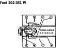
Very strange, and not logical if your car is equiped with a Ford engine. On any Ford engine, any size, the numbering of the cylinder is always done in the same way. The number 1 cylinder is the first one on the left when you look at the engine from the distributor side. The cylinder on the right of the distributor when you face it is the number 5.

The cylinder number 1 is on the right of the distibutor on all the other man,ufacturers

The cylinder number 1 is on the right of the distibutor on all the other man,ufacturers
Attachments
Your work is awesome and a great help. I will let you know if i can get equal lengths.i gave up on trying to get equal lengths !!!!
Jerry
correct and that is what is my diagram showed ?Very strange, and not logical if your car is equiped with a Ford engine. On any Ford engine, any size, the numbering of the cylinder is always done in the same way. The number 1 cylinder is the first one on the left when you look at the engine from the distributor side. The cylinder on the right of the distributor when you face it is the number 5.
View attachment 150805
The cylinder number 1 is on the right of the distibutor on all the other man,ufacturers
View attachment 150807
jerry
Question about the sensors you used. Did you use the sensors listed on the Smiths documents for oil, coolant, etc for signals to both the ECU and gauges? Since you can just program the Terminator X to work with basically anything you want. Or use multiple sensors (redundancy) for each. I only ask as I hadn't read the gauge documents and tried a test with two of the holley brand pressure transducers and it wasn't compatible.
Started drawing up a wiring pinout diagram to try and make it quicker for creating a loom and had a ohh dangit moment.
Started drawing up a wiring pinout diagram to try and make it quicker for creating a loom and had a ohh dangit moment.
Hi Douglas,Question about the sensors you used. Did you use the sensors listed on the Smiths documents for oil, coolant, etc for signals to both the ECU and gauges? Since you can just program the Terminator X to work with basically anything you want. Or use multiple sensors (redundancy) for each. I only ask as I hadn't read the gauge documents and tried a test with two of the holley brand pressure transducers and it wasn't compatible.
Started drawing up a wiring pinout diagram to try and make it quicker for creating a loom and had a ohh dangit moment.
The complete induction system complete with Terminator and harness and it sensors ( Manifold pressure, air temp, water temp, and idle air control, Injectors, coil on plug, manifold, TB. ) were supplied to me as a 'kit' from a USA Company.
The sensors for the dash gauges for oil temp and water temp and oil pressure and fuel level were supplied together with the gauges from AK.
Oil pressure sensor was mounted where the normal oil pressure switch goes on 302 but on a flexible extension and teed to a low pressure switch.
The water temp was screwed into a spare tapping on the supplied induction manifold
The oil temp sensor was screwed into as boss i welded into the bottom of the sump.
Jerry
sorry..Thanks, just what I thought, you used both as I stated/questioned.
Yes i used seperate sensors for ecu and gauges..
Yeah, because the Holley sensors are not compatible with the Smiths gauges, and the Smiths' sensors resolution is much lower compared to the Holley ones it really only makes sense to use both. I have to make a manifold for the oil input for 5 sensors lol. I am going to add a low oil pressure safety switch to kill the fuel supply if I loose the belt on the dry sump.
I have been busy just doing some odd jobs, and corrections...
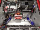
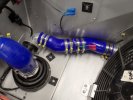
I had to move the water pump ( elec ) from front to the rear. There were too many ups and downs of pipe work and too many air traps, so much so that it would not flow correctly. So have now repositioned it at the rear , lowest point pulling off the bottom of swirl pot.. works perfect from here.
that also made room for the windscreen wash fluid tank.
picture 1 shows where it was and picture 2 shows new position
also had to change direction of flow into and out of radiator due to placement of the fan on / off thermostat.
I wanted the fans to come on as soon as water temp FROM engine was hot , not after it had gone thru rad.
Therefore input to rad is next to thermostat.
been busy on the lights as well.
Attachments

I couldn't believe it when I read your post today, Jerry. I was in the garage last night working on my build and I was thinking about the placement and orientation of my electric water pump. I was considering moving it from the front of the car to the engine bay. And then I see your post in the morning! Great minds and all that!
Anyway, great to see your progress and keep up the good work.
Rob.
Anyway, great to see your progress and keep up the good work.
Rob.
yes Rob, it just didnt work up front.. tried all sorts of bleeding and pressures but just could not remove all the air. As soon as repositioned to rear it ran like a train and gave amazing flow thru system and back into swirl pot, I had added a few 1/8 inch bypass holes in the thermostat.I couldn't believe it when I read your post today, Jerry. I was in the garage last night working on my build and I was thinking about the placement and orientation of my electric water pump. I was considering moving it from the front of the car to the engine bay. And then I see your post in the morning! Great minds and all that!
Anyway, great to see your progress and keep up the good work.
Rob.
The pump came with a 10 amp inline fuse, when I first switched it on it blew the fuse ! I measured current and found it pulled 8.5 amps constant, so on turn on the surge is much greater. I have replaced with a 15 amp and all is good.
Jerry
been doing some work on the front with regards to bump steer and castor interaction
I have made a video showing my findings and solutions.... may be of use to others ?
here it is :
Jerry
I have made a video showing my findings and solutions.... may be of use to others ?
here it is :
Davidmgbv8
Supporter
Great info will have to check my SGT 40
Hi @Jerry41 I know I'm probably missing it but where is the water pump in the first photo? I've positioned mine at the lowest point under the steering rack so just wondering if I'm going to get the same problem
Hi @Jerry41 I know I'm probably missing it but where is the water pump in the first photo? I've positioned mine at the lowest point under the steering rack so just wondering if I'm going to get the same problem
Whoops...Hi @Jerry41 I know I'm probably missing it but where is the water pump in the first photo? I've positioned mine at the lowest point under the steering rack so just wondering if I'm going to get the same problem
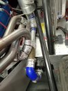
wrong picture ..should have been this one :
with it in this position it would not pull any water..i think it needed a bleed off top of hose that goes into pump to top of rad.
Much easier and logical to move to rear at lowest point and have head of water from swirl pot
Jerry
Attachments
Bill Kearley
Supporter
Depending on your build , what is shown in post 123 could be an issue. The stock firing order for 289 and 302 is 15426378
On the assumption that yours is the EWP150, and I know you've moved it down the back of the car now, but looks like that was the "poor" orientation, also it looks like you're pulling the water from the engine as opposed to pushing it (as the "out" is going into the radiator), I think the way you've got it installed the pump will be at the hottest water part, rather than the "bottom hose" as specified in the instructionsWhoops...
wrong picture ..should have been this one :
with it in this position it would not pull any water..i think it needed a bleed off top of hose that goes into pump to top of rad.
Much easier and logical to move to rear at lowest point and have head of water from swirl pot
Jerry
EWP150 instructions
Last edited:
you may be coorect and probably are..On the assumption that yours is the EWP150, and I know you've moved it down the back of the car now, but looks like that was the "poor" orientation, also it looks like you're pulling the water from the engine as opposed to pushing it (as the "out" is going into the radiator), I think the way you've got it installed the pump will be at the hottest water part, rather than the "bottom hose" as specified in the instructions
EWP150 instructions
View attachment 151755
However what i have seems to work ?
yes. it pushes water towards radiator and then to engine and sucks from the swirl pot.
IM sure there are going to be lots of people totally disagree with me but I have very good flow as seen with the rad cap off
Jerry
Similar threads
- Replies
- 20
- Views
- 3K