Chassis Setup for GT40s

i did for a moment relocate the pivot at the top about 5cm to the front and it did make a change
the idear or relocating the bottomrod is i gues necceceraly i'm going to have a look at the gtd of gerard
the ground clearence is about 5,9 inch so i can lower that also
 
Frank;
I can see that part of your problem is the attachment point at the top of the upright..and without going through a lot of changes it looks like it would be tough to fix it without altering the some of the suspension components at the top. I would think there might be a creative solution to your problem though, and I will send you a simple drawing of what may work well for you, without spending a lot of time and money. Also I am posting a photo of my upright (kind of dark though), so that you can see the vertical relationship of the radius rod pivots, and the attachment point at the top. I will send a simple drawing this evening (Tues. here now), and I hope I have helped a little with your setup.
Cheers
Phil
 

Attachments

  • 72913-UprightLR002.jpg
    72913-UprightLR002.jpg
    51 KB · Views: 264
I came opon a picture from ken saunders kva
on this picture you can see how it was intended to be
 

Attachments

  • 72942-rearsuspensionkva.jpg
    72942-rearsuspensionkva.jpg
    14.2 KB · Views: 281

Ian Clark

Supporter
Hi Peter,

You're right about keeping them clean. The PFTE lined joints do not require lubrication as such, however if you drive in dusty and or wet conditions the simplest way to clean the joint is to wash it down with a good shot of WD40 etc. This will wash off the grime or at least loosen it enough to get in there and wipe everything down dry. It also displaces moisture. I avoided the zerk fitted bearings (greasable) because of the self lubricating properties of the PTFE, however to keep it clean and tidy you'd still in there with the WD40 and shop towels...
 

Ian Clark

Supporter
Hi Frank,

See a picture (or five) is worth a thousand words! Lots of contructive input here for sure.

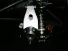
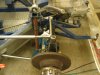
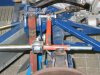
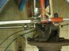
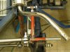
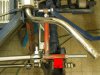
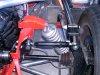
It seems like your into moving around pickup points and longer lower trailing arms to get the car sorted. The single biggest improvement will come from new pickup points for the lower reversed a-arms so that they are parallel with the ground when the car is at desired ride height.

I agree with the comments on rear castor and it looks like the rate at which your uprights will tilt backwards on bump is so severe now that introducing static height rear castor could only be done after making longer lower trailing arms, possibly shortening your upper trailing arms. The lower trailing arm should rise slightly from the upright to the chassis mounting point, not dramatically as at present.

So there's quite a challenge ahead of you. I could sort the whole thing out with accurate drawing showing all the mounting points. Drop me a private email if you like.

Depending on your intended use, the car will need more or less work. If your thinking about any track use, more rather than less. Street driver, low speed pleasure car, less work. Now is the time to get it done for sure.

Another example of a thread where loads of information is being brought to a fellow member to get through an issue, what a great resource:)
 

Peter Delaney

GT40s Supporter
Ian, thanks for that info - I was a little worried that oil-based lubes like WD40 might be a problem, but when I think about it, oil is just what gets cooked up in teflon-lined frypans, so what problem !

As you say, I guess the real trick is to really clean things after washing down so that there is no trace of oil to attract dirt.

Thanks again

Peter D.
 
Isn't it so that if i had a upright which was shorter at the bottem it would solve the problem of the top hinge point and the hight of the bootem a arm and the bottem trailing arm needs to be lowered but not so much
 

Ian Clark

Supporter
Hi Frank,

Your on the right track in regards to getting the reveresed lower arm parallel to the ground. The questions remaining are: what's easier to do and what would be the effect on the rate of camber gain, toe on bump and anti-squat?

Besides, what other uprights were you thinking about using?

Cheers
 
Ian,
Don't know yet about the uprights how about the type they use in the cav's
when i look at the picture of your car the upright seems to be about the right size
and about the work i've got about three chassisbeams in the way and my in/outlet for the cooling are in the way
these all have to be changed if i wan't to lower the lower trailing rod
i can lower it by 5cm without a problem but with the current upright if i level it it's on the floor of the chassis (if all's out of the way)and thats on ridinghight so that's about the problem
i did consider about having made new upright's but did not ask around yet
 
from the top
now you can see that i've brought the hingepoint more to the front
both the rod's are the same lenght
 

Attachments

  • 73267-IMG_1968(Small).JPG
    73267-IMG_1968(Small).JPG
    45.4 KB · Views: 245
i'd also gave the upright more caster don't know exact how much

i've checked on bumbsteer and at first sight it looks good
tommorow i'm going to set the tracking and have a look what happens
 
Frank
I was going to suggest something like you have done...I had assumed from the photos that the top hole in your upright was tapered and for something like this you would have to re-drill, unless you used a tapered bolt for attachment. It sure looks like you are on the right path. Removing that lower spacer in the front will bring you even closer, but at this point I would suggest that you try bumping out the setup and see what you have accomplished. Make one change at a time and you wont be chasing your tail so to speak. Also..if that upper bracket works for you I would suggest a second attachment point to keep it from rotating under side loads, something like this example I added to the photo..I know it is crude but it will give you an idea.
Cheers
Phil
 

Attachments

  • 73325-73268-IMG_1970(Small).JPG
    73325-73268-IMG_1970(Small).JPG
    58.3 KB · Views: 260

Howard Jones

Supporter
Here's the rear of my GTD. Please note that nothing is in single shear. Also all the ends of the movable links have a way to articulate independently, I am very worried about your attachment to the top of the hub. The load path from the link coming from the chassis mounting point to the top of the hub is all wrong.It would be a lot better to weld on a U bracket to the top of the a hub. Then run a transverse link over to the chassis. Run the other longitudinal link to another U bracket attached to the through bolt of the one on top of the A-Arm. Look at the pictures of the RF or other builders like the MDA rear.
 

Attachments

  • 73330-HPIM0136.jpg
    73330-HPIM0136.jpg
    227.1 KB · Views: 283
i've checked the bumsteer and the total range of ouline to toeline went from +/-3cm to +/-1,2cm
so that's a big improvement
the problem with the upright is that it's made of castiron that doesn't weld to good
and i saw the gtd of gerard vdhelm today so i 'd had a look how you've got it
i also saw thatthe bottem rod has got a different mounting point then the bottomarm
the spacer as yuo rever to is a part of the hinge (don't know the exact word)
 

Howard Jones

Supporter
Did you save the ball joint hole on the top of the upright when you welded on your test piece? If so you can use it to bolt on a bracket to locate to transverse link.
 
Back
Top