Chassis Setup for GT40s

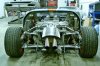
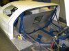
I'm in the process ofadjusting my rear suspension
the weelbase had to be made 7cm longer because of the bad fitting of the rear uprights
which are from a pantera (thanks to the former owners they made the rear carroserie shorter to fit)
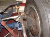
I now have the problem that when the car is on driving hight and i've made the toe 0
when i jack the wheel up all the way it toe's out and when the wheel is lowered it toe's in

I think this could be a problem caused by the bottemmounting of the upright /ubbthreads/images/graemlins/confused.gif

the bottem mounting is hart to hart 17cm from the axle down

frank
 

Ian Clark

Supporter
Hi Frank,

It would be helpful to see pictures of your rear suspension setup. What I want to see is the angle of the upper and lower control arms with the car at proper ride height.

The upper lateral links should be tilting upwards towards the tires and the lower reversed a-arms should be horizontal. I that is the case I see no reason for your problem... can you post a pic?
 

Attachments

  • 72432-1075Wide4.jpg
    72432-1075Wide4.jpg
    255.3 KB · Views: 327
as you can see the angle of the pushrod is way down and the lowerarm is also in a angle downwards
as far as i can see there are two options
- replace the rods further towards the center of the car
- replace the uprights by ones which are shorter at the bottom (the measurement from the axleline to the attachment of the lowerarm

I hope that someone's got a better idear or option

Frank
 

Russ Noble

GT40s Supporter
Lifetime Supporter
If bumpsteer is your main concern why not go to option 3 Twin parallel lower links instead of the lower A arm, or option 4 Drop the front end of the lower radius rod? /ubbthreads/images/graemlins/twocents.gif Or both?

BTW anyone running historic type race rubber on wide rims. Whats a ballpark tyre pressure?

Regards
 
Would it be possible to flip the upright over so the drop from axle to lower pivot is shorter? Then possibly relocate the chassis pivot on the upper radius arm.
 

David Morton

Lifetime Supporter
Frank,
If you are planning to run this gearbox/transmission I would have thought that it should be flipped over to allow
the drive shaft a better angle. With the suspension on full droop you already have an incline in the drive shaft. I think you may need a replacement bell housing to suit as well. my 2c worth
 
Frank,

Here are a couple of other things that may help.
If possible lower the lower inboard pick up points for the A-arms. May need to cut and fit new brackets. Looks like 3-4 cm lower would be a good starting point. Introduce some castor, that is top of uprights moved further back (would require those new brackets to be angled relative to the horizontal). Moving the front of the trailing arms in-board would also help but looks like you would need to fabricate strong (pick-up) points on the chassis. These arms take a large part of the acceleration and braking loads so take care to make them strong enough in the front-back direction if you go this route. Would not recommend inverting the upright since the lower joint will have been designed to take the bigger loads associated with the bottom outboard joint.
Maybe consider contacting one of the suspension software companies that sometimes appear on the forum, to try to get some help there. The rear geometry is a bit complex and you could find yourself going around in circles(literally) /ubbthreads/images/graemlins/grin.gif with so many things you can tweak.

Good Luck
 
Russ
I don't know what is common on having bumbsteer ( how much ?)
I do know that it affects the driving a lot so i want it to be as good as it gets
and i want to keep the overall look as genuine as possible so i wanne keep the radius rods (now i know the name of them )
lowering the bottom rod is a solution but a lot of work it means changing the cooling pipes,chassismembers,.......

spud
haven't really thought about that i'll look in to that

david
this should be the driving hight and the gearbox needs to be lifted at the engine side
so the axles are horizontal then

here another phot of the rear bay
 

Attachments

  • 72788-IMG_1904(Small).JPG
    72788-IMG_1904(Small).JPG
    53.3 KB · Views: 276
Frank,
Russ makes a valid point, those radius rods are mounted in such a position as to give you "anti squat" Which is ok but I think the mounting points are too extreme. Also I would bet that the radius rods are different lengths, which is probably your greatest problem. If you visualize the suspension from the Plan view or top, you will see that the combination of lower wishbone and radius rod forms a wishbone in itself, the same with the transverse link and raduis rod at the top, if these two elements are swinging in different radii the result is a change at the mounting point. Since the chassis can't move your upright will. Also the mounting points at the upright are different as viewed from the side, so even if you correct the two radius rods you will still get some bump. I have bben thru this problem and we semi-solved it by adding some bracketry to the upper radius rod mount to bring the pivot point out closer in plane with the lower mount. I still have some bump, but negligable, and it is in the extremes of travel. If you can acheive it try to make any bump steer you have toe in the wheel, as toeing out will greatly affect control. I hope some of this helps.
Cheers
Phil
 
i've thought about it myselff and it is a option but need to make change's to my chassis and i was hoping that there could be a easier way of fixing it (wishfull thinking ofcourse)
what is your ground clearence ?

Frank
 

Russ Noble

GT40s Supporter
Lifetime Supporter
Well, there is going to be no easy quick fix, but in view of what you've said the simplest solution is parallel bottom links to replace the A arm. This will eliminate the toein/out as the bottom of the upright moves backward and forwards due to the extreme angle of the lower radius rod. It looks like there is already a frame out the back to which some brackets could be attached relatively easily to accomodate the rear link.Hope this helps.

Regards
 
Thought you might like to see a sketch of the original GT40 concept. Interesting to see the amount of anti-squat (inclined lower trailing arm)also the amount of castor (tilt of rear upright)
 

Attachments

  • 72805-scan.jpg
    72805-scan.jpg
    259.2 KB · Views: 359
Frank
I assume you were asking for my ground clearance...I have it set at 5". Also as Trevor said caster may help a bit...I have seen some replicas,(ERA in particular) with large amounts of caster in the rear uprights. I am assuming that this was done to eliminate bump steer, but I would think there is always some there. The saving grace here is that suspension travel on most 40's is not too great, and this in itself would limit how much bump steer you would get. Also, from the photos I can't see your mounting point at the top of the upright, and the forward mounts at the chassis. I mention this because the forward mounts not only pivot about the bolts, but also swing in an arc twisting the radius rod as the suspension moves...this can be an area where binding will occur, and it may introduce other movements and/or limit travel while causing excess wear on the mounting points. I know this is probably more than you wanted to deal with, but if you get a good chassis man to look at that setup you have, a few minor modifications may put you in the ballpark. I hope all of this helps.
Cheers
Phil
 

Howard Jones

Supporter
You should plot camber change though the travel range. Start with -1 degree at normal ride height. Use 5" at rear. It should go to about -5 degrees MAX at full bump (suspension compressed).

Just looking at your picture I think you might want to try dropping the inboard lower A Arm mount to inline with the bottom of the chassis. Just clamp the bracket in place and re-run plot. You might get a better half shaft alinement also. Look again at the picture above yours. Bottom A Arms horizontal as are the driveshafts.
 

Peter Delaney

GT40s Supporter
Ian - A quick question (slightly off-topic, but probably relevant) :

You mentioned PTFE (teflon) rose joints :

---------------
"We're running .750 bore Aurora Monoballs with PTFE liners on our updated suspension systems and Aurora Rod Ends (PTFE) for the toe adjuster too.

I was concerned about ride quality, however it hasn't been a problem and the teflon lined balls should last along time in street use when kept clean and lubricated."
----------------

I have just replaced all the rose joints in the rear of my car (at great expense, but well hidden from the Auditor !) with teflon-lined aircraft-grade ones from National Bearings. The reduction in clunks & rattles is VERY noticeable & the ride is definitely smoother.

But I am intrigued by your comment re lubrication. My supplier, who only handles bearings, said "Clean, clean, clean" is the major message for long life, but also suggested no lubrication (other than water when washing).

What would your recommendation be regarding lubrication of teflon joints ?

Kind Regards,

Peter D.
 
Back
Top