
You are using an out of date browser. It may not display this or other websites correctly.
You should upgrade or use an alternative browser.
You should upgrade or use an alternative browser.
Chuck and Ryan's RCR Build
- Thread starter CESLAW
- Start date
VIDEO ON YOUTUBE? :laugh:
We contemplated a video of the system, but it would have been a silent movie. So we figured, what's the point.
Chuck and Ryan;
April 1st must be a really important day at your house......................
Not as good as last year but close! I really did enjoy it.
Keith
Believe me, he has had this planned for a while now :thumbsup:
Wiper Arm Installation
Now seriously, how many plan to drive their GT in the rain? The car is not watertight. Even if one diligently applies weather stripping around the door opening, there are plenty of places where water can intrude, like the side window vents. After all, this is a race car, not a Buick. Accordingly, a windshield wiper on this car serves three functions, in order of importance: (1) To meet the requirements for registration in most states; (2) Looks like the original; and (3) Maybe once or twice in the cars life it may actually be used to shed rain droplets. So this project was put on the lower end of the “B” list.
The wiper kit provided with the RCR is the “It’s a Snap” brand. We previously detailed the installation of the motor and drive assembly. Finding a wiper arm that worked prove to be a real challenge. We tried several different wiper arms before finally finding one that worked well. The problem is the fitting on the Snap It drive shaft that connects to the wiper arm.
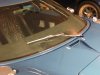
We wanted a wiper arm that would look reasonably original. Thus it needed to be stainless and simple in appearance. We found that a 1965 Mustang wiper and 16” blade looked much like the GTs depicted in the Ford That Beat Ferrari. Admittedly, the original had a straight arm while the Mustang has an angle, but the Mustang arm sets well when parked. Tony Branda Mustang Parts, 800-458-3477, part number WIPE 1 and WIPE 5, or Mustangs Plus Restomod, Mustangs Plus are good sources.
But there is a problem. The Snap It wiper drive shaft comes with a half inch knurled fitting, but the wiper arm requires a 5/8” knurled fitting. After a lot of searching we finally found a wiper arm at NAPA that had a workable fitting. NAPA Part number 60-725. This is an adjustable arm which will work by itself. Both the angle of the arm and the length of the arm can be adjusted. There is no need to use the Mustang arm noted above. But the NAPA arm is not polished like the Mustang arm and the adjustable angle gives it a ‘universal’ fitting look rather than a custom look. So I would suggest getting the NAPA arm, check it out, and then decide if the very small aesthetic difference offered by the Mustang arm is worth it. The Mustang arm is 15” long. The NAPA arm is adjustable from approximately 14” to 17”, giving the NAPA arm a bit more reach.
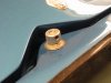
The key to the NAPA arm is the knurled fitting. If you order the Mustang arm the knurled fitting is the only piece you will use. But the fitting needs to be modified. First, the center hole must be drilled out to fit the drive shaft. Second, a hole needs to be drilled and tapped to fit a set screw so the knurled driver can be locked in place.
The wiper has a good arc of travel and an appropriate reach. The spring is strong and holds it snug against the windshield. If one actually gets caught in the rain it should do the job.
Another hint: If you wired up the “park” feature on the wiper switch, disconnect it. It is easier to shut off the wiper when the arm is where you want it. When parked, put it in the horizontal position. But on the track, put it in a vertical position to reduce drag and prevent it from bouncing around at 150 mph (just like the originals).
The first photo shows the knurled fitting, drilled and tapped for the lock screw. The other pictures show the Mustang arm and 16” blade.
Now seriously, how many plan to drive their GT in the rain? The car is not watertight. Even if one diligently applies weather stripping around the door opening, there are plenty of places where water can intrude, like the side window vents. After all, this is a race car, not a Buick. Accordingly, a windshield wiper on this car serves three functions, in order of importance: (1) To meet the requirements for registration in most states; (2) Looks like the original; and (3) Maybe once or twice in the cars life it may actually be used to shed rain droplets. So this project was put on the lower end of the “B” list.
The wiper kit provided with the RCR is the “It’s a Snap” brand. We previously detailed the installation of the motor and drive assembly. Finding a wiper arm that worked prove to be a real challenge. We tried several different wiper arms before finally finding one that worked well. The problem is the fitting on the Snap It drive shaft that connects to the wiper arm.
We wanted a wiper arm that would look reasonably original. Thus it needed to be stainless and simple in appearance. We found that a 1965 Mustang wiper and 16” blade looked much like the GTs depicted in the Ford That Beat Ferrari. Admittedly, the original had a straight arm while the Mustang has an angle, but the Mustang arm sets well when parked. Tony Branda Mustang Parts, 800-458-3477, part number WIPE 1 and WIPE 5, or Mustangs Plus Restomod, Mustangs Plus are good sources.
But there is a problem. The Snap It wiper drive shaft comes with a half inch knurled fitting, but the wiper arm requires a 5/8” knurled fitting. After a lot of searching we finally found a wiper arm at NAPA that had a workable fitting. NAPA Part number 60-725. This is an adjustable arm which will work by itself. Both the angle of the arm and the length of the arm can be adjusted. There is no need to use the Mustang arm noted above. But the NAPA arm is not polished like the Mustang arm and the adjustable angle gives it a ‘universal’ fitting look rather than a custom look. So I would suggest getting the NAPA arm, check it out, and then decide if the very small aesthetic difference offered by the Mustang arm is worth it. The Mustang arm is 15” long. The NAPA arm is adjustable from approximately 14” to 17”, giving the NAPA arm a bit more reach.
The key to the NAPA arm is the knurled fitting. If you order the Mustang arm the knurled fitting is the only piece you will use. But the fitting needs to be modified. First, the center hole must be drilled out to fit the drive shaft. Second, a hole needs to be drilled and tapped to fit a set screw so the knurled driver can be locked in place.
The wiper has a good arc of travel and an appropriate reach. The spring is strong and holds it snug against the windshield. If one actually gets caught in the rain it should do the job.
Another hint: If you wired up the “park” feature on the wiper switch, disconnect it. It is easier to shut off the wiper when the arm is where you want it. When parked, put it in the horizontal position. But on the track, put it in a vertical position to reduce drag and prevent it from bouncing around at 150 mph (just like the originals).
The first photo shows the knurled fitting, drilled and tapped for the lock screw. The other pictures show the Mustang arm and 16” blade.
Attachments

Rob
Lifetime Supporter
Chuck,
You guys kill me. Reviewing your log today for the first time in a while, so didn't exactly have 4-1 on the mind....sooooo will admit (again) you had me going for a bit there. Your gags are just too thorough. Just when I'm saying this must be a prank, I realize there's a schematic. Oh....maybe they really did try this....:veryangry: Damn it... they did it to me again.
Anyway... nice job on the wiper. Looks great.
Parking Brakes I
How we installed the parking brakes was posted a very long time ago. Since then RCR has added an angle bracket to the mix, we discovered an issue with the clearance between the calipers and the wheels, and adjustment issues needed to be addressed. So we thought it best to just start over.
Brake Handle
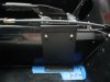
The parking brake handle assembly was installed. We painted the steel bracket low gloss engine black. The aft holes securing it to the chassis were drilled two inches forward of the point where the floor and back panel meet. The bracket was assembled using the upper holes in order to clear the shifter cables.
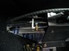
Note there may be a clearance issue between the seat bottoms and the bolts that hold the brake bracket to the floor. We countersunk one of the bolts on the passenger to address this issue. The other three bolts were not a problem. (See picture).
We routed the upper shifter cable over the brake bracket. Make sure the cables do not rub on the brake linkage. The shifter looks a bit ungainly once it is in place, but it is a nicely engineered assembly, it is good and solid, and once the aluminum cover is in place it will look like it belongs.
Cables
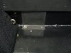
The brake cables were installed. Two holes were drilled on the fire wall either side of the shifter cables hole.
Be sure to fasten the short connecting cable to the lower attachment hole on the brake handle. It will give you a greater arc of travel than the top hole.
An angle bracket is now available from RCR that routes the cable from the chassis to the caliper in a straight line resulting a cleaner assembly, reducing the risk of the cable coming in contact with the tire. If you don’t have these angle brackets, give Fran a call. They are an easy addition.
But the angle brackets shorten the distance between the cable housing and the caliper which means the spring on the cable end becomes rather tightly compressed. We cut two inches off the spring. Here is a really big tip: don’t pull the inner cable out of the shield to remove the spring. It is VERY hard to get the cable back in because of the sharp angle it makes just before it passes through the fire wall. Instead bend the spring loose at the chassis end (not the caliper end) and untwist about two inches off and then cut it.
Calipers
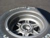
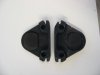
After a few miles of driving we began to hear a grinding sound. The monocoque chassis makes it difficult to isolate where sounds are coming from. We initially though it was coming from the front, but soon discovered it was coming from the parking brake calipers rubbing against the inside of the wheels on both sides. We removed the calipers and ground down the ‘wings’ that protruded from the sides of the calipers opposite where the cable attaches, repainted it with high heat paint and reassembled it. One may want to do this before the initial installation and save themselves some potential headaches later on. The clearance is tight.
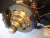
A picture of the trail left on the inside of the wheel is attached. A picture of calipers, one before and one after, is attached. Finally a picture of the caliper installed shows the revised surface on the top, outer portion.
When securing the cable to the caliper, one can position the “L” bracket either forward or backward. We positioned it forward.
The brackets that hold the calipers had an extra bit of steel welded on the end that slides into the caliper. This extra bit of steel should be position away from the brake disc – towards the center line of the car.
How we installed the parking brakes was posted a very long time ago. Since then RCR has added an angle bracket to the mix, we discovered an issue with the clearance between the calipers and the wheels, and adjustment issues needed to be addressed. So we thought it best to just start over.
Brake Handle
The parking brake handle assembly was installed. We painted the steel bracket low gloss engine black. The aft holes securing it to the chassis were drilled two inches forward of the point where the floor and back panel meet. The bracket was assembled using the upper holes in order to clear the shifter cables.
Note there may be a clearance issue between the seat bottoms and the bolts that hold the brake bracket to the floor. We countersunk one of the bolts on the passenger to address this issue. The other three bolts were not a problem. (See picture).
We routed the upper shifter cable over the brake bracket. Make sure the cables do not rub on the brake linkage. The shifter looks a bit ungainly once it is in place, but it is a nicely engineered assembly, it is good and solid, and once the aluminum cover is in place it will look like it belongs.
Cables
The brake cables were installed. Two holes were drilled on the fire wall either side of the shifter cables hole.
Be sure to fasten the short connecting cable to the lower attachment hole on the brake handle. It will give you a greater arc of travel than the top hole.
An angle bracket is now available from RCR that routes the cable from the chassis to the caliper in a straight line resulting a cleaner assembly, reducing the risk of the cable coming in contact with the tire. If you don’t have these angle brackets, give Fran a call. They are an easy addition.
But the angle brackets shorten the distance between the cable housing and the caliper which means the spring on the cable end becomes rather tightly compressed. We cut two inches off the spring. Here is a really big tip: don’t pull the inner cable out of the shield to remove the spring. It is VERY hard to get the cable back in because of the sharp angle it makes just before it passes through the fire wall. Instead bend the spring loose at the chassis end (not the caliper end) and untwist about two inches off and then cut it.
Calipers
After a few miles of driving we began to hear a grinding sound. The monocoque chassis makes it difficult to isolate where sounds are coming from. We initially though it was coming from the front, but soon discovered it was coming from the parking brake calipers rubbing against the inside of the wheels on both sides. We removed the calipers and ground down the ‘wings’ that protruded from the sides of the calipers opposite where the cable attaches, repainted it with high heat paint and reassembled it. One may want to do this before the initial installation and save themselves some potential headaches later on. The clearance is tight.
A picture of the trail left on the inside of the wheel is attached. A picture of calipers, one before and one after, is attached. Finally a picture of the caliper installed shows the revised surface on the top, outer portion.
When securing the cable to the caliper, one can position the “L” bracket either forward or backward. We positioned it forward.
The brackets that hold the calipers had an extra bit of steel welded on the end that slides into the caliper. This extra bit of steel should be position away from the brake disc – towards the center line of the car.
Attachments
Parking Brakes II
Adjustment
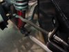
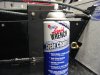
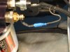
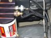
The cable needs to be adjusted. We set the caliper end about midway on the threaded portion of the cable. The remaining adjustment was at the brake lever. We found that the cable was about three inches too long, due to the addition of the angle bracket and the location of the brake handle. We clipped off the cable stops and replaced them with adjustable cable stops. Be sure to add a washer or sleeve between the cable stops and the plate to fill the recess or the cable will slide out of the slot on the side. With a bit of adjustment we were able to get them to hold securely with the brake handle pulled up about two thirds of its travel.
The adjustment screws on the calipers for the pads have a coarse thread. Just a fraction of a turn will go from slack to locked up tight. We snugged them up until they stopped the wheel from turning, then backed it off about an eighth of a turn so they would turn freely then tightened the lock nut. One can just juggle the caliper assembly a bit.
The cable needs to be lubricated. One does not want to use ordinary oil since it will gum up the cable over time. We used a chain / cable lubricate, Gunk Liquid Wrench. It worked very well made the cable slide much more smoothly.
Adjustment
The cable needs to be adjusted. We set the caliper end about midway on the threaded portion of the cable. The remaining adjustment was at the brake lever. We found that the cable was about three inches too long, due to the addition of the angle bracket and the location of the brake handle. We clipped off the cable stops and replaced them with adjustable cable stops. Be sure to add a washer or sleeve between the cable stops and the plate to fill the recess or the cable will slide out of the slot on the side. With a bit of adjustment we were able to get them to hold securely with the brake handle pulled up about two thirds of its travel.
The adjustment screws on the calipers for the pads have a coarse thread. Just a fraction of a turn will go from slack to locked up tight. We snugged them up until they stopped the wheel from turning, then backed it off about an eighth of a turn so they would turn freely then tightened the lock nut. One can just juggle the caliper assembly a bit.
The cable needs to be lubricated. One does not want to use ordinary oil since it will gum up the cable over time. We used a chain / cable lubricate, Gunk Liquid Wrench. It worked very well made the cable slide much more smoothly.
Attachments

Ron McCall
Supporter
Don't tell Ryan I posted this picture of him and Cortni heading off to prom . . . . .
Ryan is one BAD MF'er!!!!!!
What a perfect way to attend the prom!!
Chuck, that is a great picture and when thay ask him at the prom where he rented it Ryan can say my Dad and i built it . great job again Bob
plus, i would guess that it's pretty difficult to do the "bump and grind" in the '40....
Yeah, not much chance of getting her pregnant in the back seat.....
Instrument Calibration
This applies only to the RCR cars that use the Classic instruments. This is a really tiny detail.
We noticed that the oil temperature gauge seemed to be reading high. It typically indicated 220 to 230 degrees with normal driving. Yet the infrared temprature sensor showed about 190 to 200 on the outside of the sending unit and the oil from the dip stick could be run through one’s fingers with out burning. So we decided to drop the readings about 20 degrees or so.
The temperature sensors used by Classic instruments change resistance with variation in temperature. As the temperature rises the resistance decreases. So increasing the resistance will cause the gauge to read lower. We used a pair of 47 ohm, quarter watt, resistors in parallel, which is about 24 ohms net resistance, covered with heat shrink and inserted them between the pick up wire and the terminal using removable plugs, so it can be easily changed in the future. (A single half watt resistor would have been easier to use, but none were available locally in the 20 to 30 ohm range). The result was about a 20 degree drop in the reading. Now it reads between 200 and 210 under normal operating conditions, which should be closer to accurate.
The same technique could be used for the water temperature gauge, although ours appears to be reading accurately.
Attachments
Chuck,
Do think your temp gauge might just be the exception? It would be nice to know if that were the case... anyone, anyone Ferris Bueller? :thinking::thinking:
Do think your temp gauge might just be the exception? It would be nice to know if that were the case... anyone, anyone Ferris Bueller? :thinking::thinking:
Chuck,
Do think your temp gauge might just be the exception? It would be nice to know if that were the case... anyone, anyone Ferris Bueller? :thinking::thinking:
Can't say if it is the gauge or the sending unit. Could have swapped out sending units to find out. But a couple of resistors cost less than a buck, so it was an easy adjustment regardless of the cause. I would hope that this is the exception and that the Classic gauges and corresponding sending units are accurately calibrated.
But note also the non linear scale on the oil temp gauge. Over 200 degrees a small movement of the needle makes a big difference in the reported temp, so slight calibration errors would look more significant.
I generally consider the temp and pressure gauges as providing good relative indications, not absolute indications. I usually don't get too concerned about the readings once I get a sense of where they generally set under varying condition. But the incorrect high oil temperature reading just bugged me, hence the fix.
I am sure that installation variations and calibration errors will cause variations from one to another regardless of the quality of the gauge. But I am no expert on gauges.
If one were really anal, the sending unit could be droped in a cup of near boiling temp with a thermometer and compared to the gauge reading before the senders are permanently installed.
Similar threads
- Replies
- 0
- Views
- 538
- Replies
- 1
- Views
- 459