Custom transaxle

I have just realised you boys are on the NZ$ which means you are getting every thing done for half the price of us here in the UK, when we work with the US$ here it works out £1 to the $ by the time all the transport and duty`s are paid.

Bob
 
Thanks Jac, I need to get hold of some CVs and do some fitting to see if I can find some that will fit the Nissan axles. The reason I'm so keen to keep with the Nissan stuff (beside the fact my hubs are made to suit them) is they do Chromoly ones that are super strong and have the flex you talk about, they will take 8500 ftlbs at a 30 degs before failure and the CV fails not the axle. I'll keep researching. Cheers Leon.
 
The problem for us is it cost's a bloody fortune in freight to get stuff or to sent it when finished. Good thing my labour is cheap.

Cheers Leon.
 
I have just realised you boys are on the NZ$ which means you are getting every thing done for half the price of us here in the UK, when we work with the US$ here it works out £1 to the $ by the time all the transport and duty`s are paid.

Bob

Bob all those prices I've mentioned for parts are in US$.... Our Kiwi $ floats and IIRC we get ~80/88 US cents for NZ$1.00 in recent times....so you have to pick your moments when to buy, then we have freight, duty gst etc .
 
One other thing to keep in the back of your mind Leon regarding axles, 1 I wouldn't use second hand ones unless you no 100% what side of the car they came of, and then which end went where, cause as Jac so eloquently said they, [axles] do twist, and if you take a used set and they go on opposite to how the were originally they will break, and I mean when, not if. my advice is to mark the axles when you first install them so they never get mixed up.
cheers John
 
Good advise John, if Commodore ones will work I will buy New as they are reasonably priced. There are a couple of other options I'm going to look at as it would be nice to find somthing I can just drop the complete shaft and CVs in with no mods.

Leon.
 
Leon there are quite a lot of super tough diff units out there that come with the flanges for the larger cv`s. BMW large case diff has a 3.1 ratio ,lsd and 108 mm flanges . Thats a few boxes ticked and they change hands here for around £150.


Here is one I bought for the hicost


Bob
 
Last edited:
I just had a look on Trademe out of interest at BMW diffs and it looks like they go from $300 up for a big case. They look like they have a small pinion/centre line offset but I have been caught before where the photos don't give a real indercation, can you tell me what the Hypoid off set is on those units also what size the crown wheel is. I like the way the stud axle appears to be housed in its own bearing housing that bolts to the diff housing, is this in fact how it is set up or does that flange just hold the seal in place. Appreciate your feed back Bob.

Cheers Leon


Will do, I will pop the rear cover off one and have a measure up + piccies.

Bob
 
Well today is the day, Finally finished the Transaxle main case pattern and heading off to the Foundry with it now. they say I should have the casting back in about 3 weeks which is about when I'm off to work again so probably won't see much progress for a while but at least it will finally be in alloy. Some pics of the finished pattern.

Cheers Leon
 

Attachments

  • IMG_2670.jpg
    IMG_2670.jpg
    148.9 KB · Views: 463
  • IMG_2671.jpg
    IMG_2671.jpg
    146.8 KB · Views: 341
  • IMG_2672.jpg
    IMG_2672.jpg
    140.6 KB · Views: 389
  • IMG_2673.jpg
    IMG_2673.jpg
    141.1 KB · Views: 413
Nice work Leon. I dont think there are many folk out there that could appreciate the amount of work that goes into mold making let alone the brain ache of the trans itself.:thumbsup:

Bob
 
Leon
Just curious, My son works on an oil rig just out of Melbourne, is that similar to where your at. He is away 3 weeks hard out then home to NZ for 3 weeks or r & r. Gives him good solid project time.
Cheers
Russell
 
Hi Russell,
Similar to me I'm now based back in NZ but I was in WA and QLD I was doing 4 on 4 off so yes good project time but I also do a bit of driving when I'm home to fund the project.

Cheers Leon
 
Leon
Next time we are down to see him, I will try to make contact. The rig Jeff is on has just been shifted from NZ to Australia and they are way behind the 8 ball setting it up so long hard hours getting there.
Cheers
 
I picked up the raw casting from the foundry today, they said it was quite a challenge to get all the pieces together and get it poured. It was made up of a total of 10 sections all locked together. The surface has a nice smooth finish and once I have cleaned all the runners off it and machined the main faces we will fine sand blast it to give it a nice finish, I may paint it satin black we will see how it looks. I put it in the lathe and started with the first face where it will bolt to the B/H once I have finished that end I will turn it around and face off the rear surface for the rear bearing carrier.
I have a couple of shots of it set in the lathe.

Cheers Leon
 

Attachments

  • IMG_2681.jpg
    IMG_2681.jpg
    161.6 KB · Views: 608
  • IMG_2684.jpg
    IMG_2684.jpg
    144.8 KB · Views: 443
  • IMG_2685.jpg
    IMG_2685.jpg
    136.5 KB · Views: 406
  • IMG_2686.jpg
    IMG_2686.jpg
    144.7 KB · Views: 586

Terry Oxandale

Skinny Man
Very exciting to finally see you have a casting in-hand. I'm not very knowledgeable about a lathe, so I assume it was a challenge to chuck this up in the correct location (axis) to ensure all the cutting and indexing was perfect? How or what did you use to ensure this was correct?
 
Hi Terry,

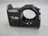
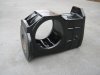
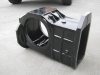
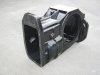
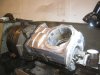
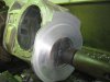
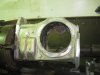
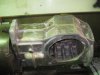
The first step is pretty simple but very important as it sets the axis for the whole thing and that is to get the First face cut square with main shaft axis once that is done then everything is set from that surface. To do this I set it in the 4 jaw roughly where it should be, get the centre on the face marked where the input shaft will go and then adjust the chuck so the live centre in the tailstock is lined up. then with that held by the tailstock I readjust the chuck end so that the five relevant surfaces ( Top, Bottom, both side plate, and the B/H surface) are level and I use a sprit level to do this, then I face off the B/H surface. From this point on everything will be square to that surface. I hope that makes it a little clearer, I'm quite sure if it were being done in a flash state of the art machine shop they would have some fandangle laser beam show to do it all but I don't have that so it a case of measure, check, remeasure and recheck.

Cheers Leon
 
Leon, someone told me that you should not machine to finish size at this stage as the casting will move around a bit during the machine work, even consider giving it a few temp cycles to allow casting to 'relax' a bit.
 
Leon, someone told me that you should not machine to finish size at this stage as the casting will move around a bit during the machine work, even consider giving it a few temp cycles to allow casting to 'relax' a bit.

Ours were always heat treated LM25 so the oven process was done at the foundry. On some of the prototypes we skipped the heat treatment and the guys that did the machining kicked off because it wont machine nicely.

Bob
 
Back
Top