Here is Dick's e-mail: [email protected]
I copied him on your post. I hope you and Dick can connect- the Sabel was nice car.
I copied him on your post. I hope you and Dick can connect- the Sabel was nice car.


")
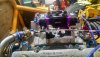
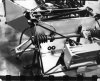
 The idle is much too high and can't be adjusted any lower. I think my carb has a serious problem so I ordered a new Proform black race series 850 cfm to replace the old Holley 850 "double-pumper".
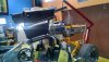
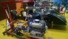
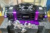
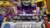
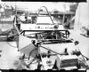
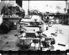
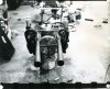
 Biggest problem with Holleys (I’ve built hundreds over the years) is corrosion in the emulsion tubes inside the metering blocks. There really is no good way to remove them for cleaning. I’ve tried many solutions and even ultrasonic cleaning with a marginal success rate.Having determined that my old "bargain" Holley DP 850 was shot, I ordered a new Proform 850 to replace it and it arrived yesterday evening by FedEx. It looks a lot nicer that the old cast zinc Holley and it has a four-corner idle adjustment which the Holley did not have. I can't say much in favor of its tarty black & purple tarty color scheme but I'll mount this on my engine and fire it up on Saturday.
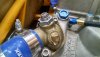
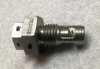
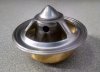
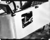
The replacement ACDelco thermostat also arrived today and I checked it in a pot of boiling water. It opened about 1/4" so it is OK, unlike the one I just removed. It has a small air bleed hole to make expelling air when filling the cooling system easier.