Jason's Coyote Powered RCR40 Downunder

To avoid confusion, this inlet manifold which is an absolute work of art, is all credit to the guys at InnoV8 (ire.net.au) - while we are proud to be associated and a distributor for them, all credit goes to them for the design, manufacture and supply of this manifold.

regards Paul RF
 
Thanks for making that clear Paul. The guys at InnoV8 are also very helpful and have assisted me with some great engine tips. Thanks guys.

Transaxle and Engine Coolers (I would appreciate some advice)

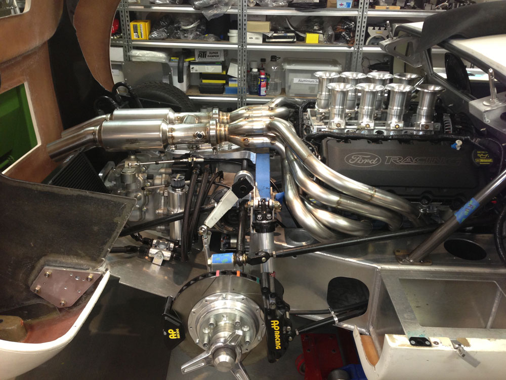
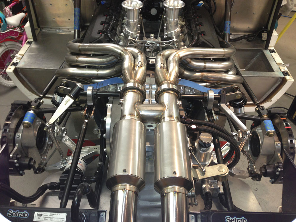
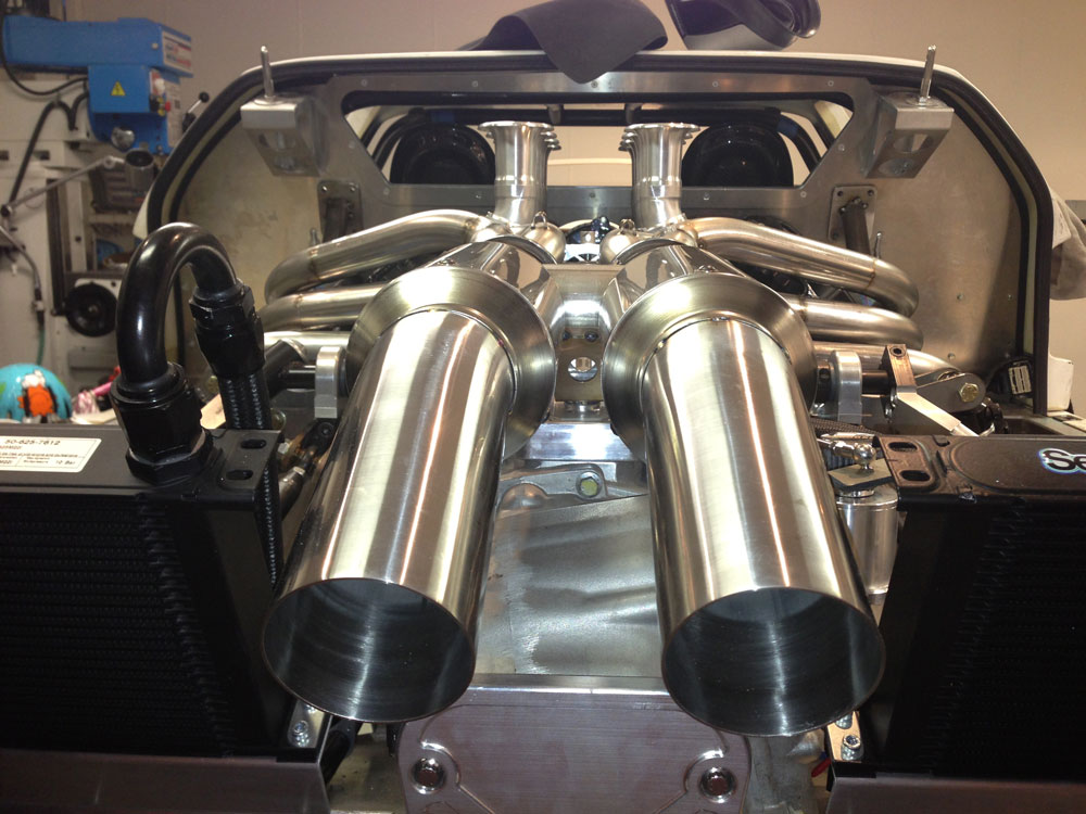
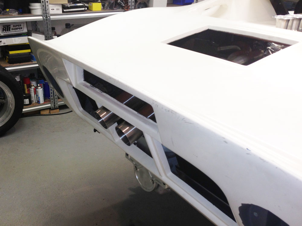
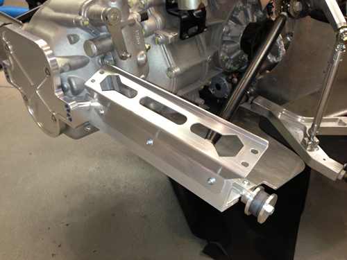
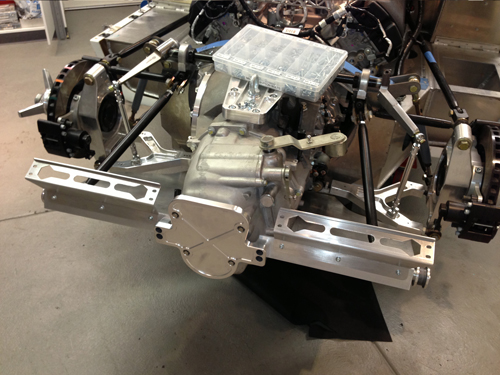
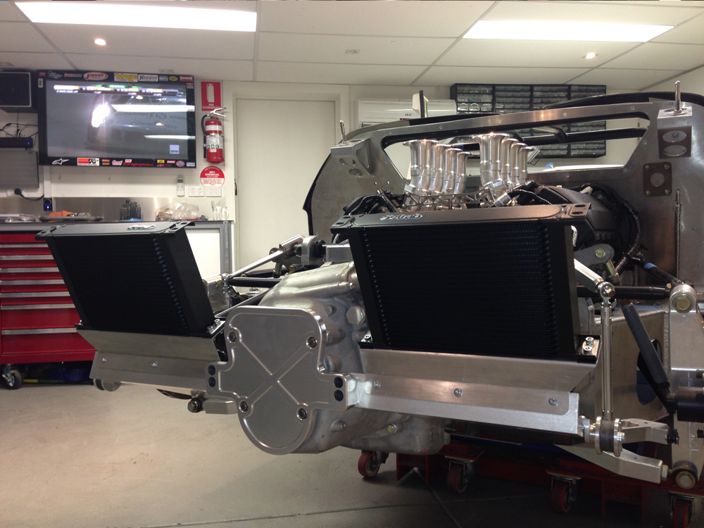
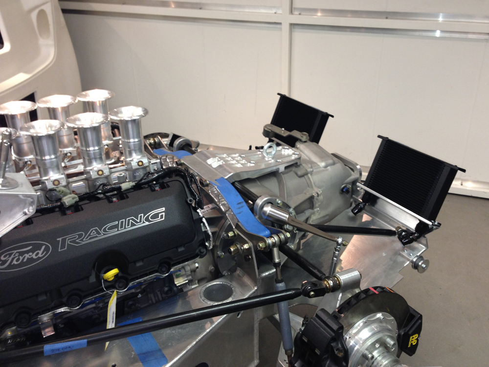
I decided to fit air to oil coolers, I was looking at a Laminova water to oil cooler but was worried about routing hoses to the front of the engine. I decided to fit air to oil coolers at the rear for mostly visual reasons. I wanted to see radiators through the back of the car! I do not plan on fitting any alloy covers on the rear clip. Brackets were made out of 2.5mm aluminium to mount the coolers.

Coyote-Engine-in-GT40-oil-coolers1.jpg


Coyote-Engine-in-GT40-oil-coolers2.jpg


I also decided to go with the same size coolers one of which is over sized for the transaxle. This was only done for symmetry when looking at the rear of the car. A pretty bad reason but what the hell!

Coyote-Engine-in-GT40-oil-coolers3.jpg


Coyote-Engine-in-GT40-oil-coolers4.jpg


Secondary cooler stabilisation will follow. Orientation of the coolers was checked with Setrab and they replied in detail on why it is not an issue at all. Great service from them on this, very helpful.

I have a Mocal thermostat for the transaxle (thanks for the tip Fran) which will help warm up the oil so that side is fine. Transaxle lines are AN-10 and engine in AN-12.

I also have a thermostat for the engine side but I do not know if I should use it?

Up Sides of fitting an engine thermostat
1) Faster warm up
2) I don't have a spare thermostat!

Down sides
1) Fitting the thermostat and remote oil filter on the rear alloy panel is BLOODY tight. It will be a mess of hose.
2) Creates an oil flow restriction. Even with my upgraded billet oil pump this is a concern as highlighted by Tom.
3) Uses more fittings and therefore more potential leak points.

Any help with this decision would be greatly appreciated.
 

Dimi Terleckyj

Lifetime Supporter
Hi Jason
Nice work mate.
One small detail you should keep in mind is that the top of the oil coolers will need to be firmly braced because when they are full of oil they will have some weight and as they are leaning at an angle will have a tendency to develop fatigue cracking.

Oil coolers need to be held on both sides of the core.

Dimi
 
Thanks for the kind comment Dimi.

Regarding the additional brackets I have noted in the post that "Secondary cooler stabilisation will follow". I don’t want to just throw stays down to the alloy plate unless I have to, I would like to try do something integrated with other brackets and for that I will need to wait for the exhaust system.
 
Extractors

Work to develop an extractor system focused on performance has been undertaken recently. Moving to a non cross-over system and targeting the right primary length was a priority. It is equipped with a H-pipe and setup with the optimum primary tube diameter for my engine and cam configuration. Design was developed using an exhaust simulation program to determine primary size and length. Roaring Forties in Australia fabricated the first side below to meet the requirements I set. I think they did a great job with limited space. Four different bend radius tube configurations were sourced from the USA to facilitate a design that looked fairy "organic" and allowed the system to fit in a car with little room due to the large Coyote engine and huge Ricardo transaxle. Equal length is achieved as far as practical. Work to finish the other side and the custom race mufflers will continue soon.

GT40-Extractors-1.jpg


GT40-Extractors-2.jpg


All tubing is stainless steel and it will be double ceramic coated on the inside to control the temperature in the engine bay.
 
Last edited:
Hi Jason,Conrad here.I see your raising the bar yet again.Pipes look great as do the intakes .lt is good to see you using all available space under the rear body.I like your idea of mounting the oil coolers too.Have been busy making body moulds off our body panels.Have fitted a ford Windsor Audi box and exhaust into the rolling chassis,starting to look like a car.Good to see your car coming together .Keep up the great work.Cheers Conrad.
 
When this is done, I know several of us Coyote/Aluminator folks who would really like the schematics (or anything you can supply) for the headers. :)


Extractors

Work to develop an extractor system focused on performance has been undertaken recently. Moving to a non cross-over system and targeting the right primary length was a priority. It is equipped with a H-pipe and setup with the optimum primary tube diameter for my engine and cam configuration. Design was developed using an exhaust simulation program to determine primary size and length. Roaring Forties in Australia fabricated the first side below to meet the requirements I set. I think they did a great job with limited space. Four different bend radius tube configurations were sourced from the USA to facilitate a design that looked fairy "organic" and allowed the system to fit in a car with little room due to the large Coyote engine and huge Ricardo transaxle. Equal length is achieved as far as practical. Work to finish the other side and the custom race mufflers will continue soon.

GT40-Extractors-1.jpg


GT40-Extractors-2.jpg


All tubing is stainless steel and it will be double ceramic coated on the inside to control the temperature in the engine bay.
 
When this is done, I know several of us Coyote/Aluminator folks who would really like the schematics (or anything you can supply) for the headers. :)

^ What he said :D (If you're willing to share)

Beautiful build. Every piece is a work of art. Keep it up!
 
Jason,
You asked for some advice on the oil thermostat. here are my suggestions. First let me say you need a thermostat. Your oil will not get up to operating temps or will take a long time to get there. Now comes the important part. Where do you put all this stuff. Canton makes a nice filter adapter#22-595 (1/2"npt fittings with 3/4x16 filter threads. This is a side fittings adapter so it rotates 360 degrees for optimum line placement in a tight fitting bay. The next thing you will need is a Permacool single filter head #1791 (1/2 npt fittings with the 3/4x16 filter threads).
This has a base plate on the side for easy mounting. It also has 4 ports for in and out. The main out port should go to the next item the thermostat. 1 of the two extra ports I use for oil pressure reading and one for oil temp readings. On the oil pressure reading side I also have a low oil pressure safety switch that will shutdown my fuel pumps if the pressure drops below 5 psi.You can't be looking at the gauges all the time! That switch also allows for a bypass switch for easier start up rather than the engine spinning til the pressure builds. The last thing you will need is the mocal remote thermostat(AOT2) which would be mounted after the filter and before the cooler. Mocal oil thermostats are designed to regulate oil flow through cooling devices until optimal (minimum) temperatures are reached. Cold oil enters the thermostat and is bypassed through the center of the unit returning to engine. During warm-up the thermostat never closes off oil flow to the cooler, rather, it offers a less restrictive path for the oil to flow allowing the cooler to acclimate to system temperature. As oil warms to 180 degrees (200 in high temp versions) the operating "waxstat" closes the bypass permitting full flow to the cooler. I would suggest that with this you will need a one way flapper valve on the outflow of the cooleer that would insure the proper flow to the cooler once the thermostat opens completely. They say you don't need it, but I want to know the flow is getting to and from the filter. It also prevents back flow. If you plan to track the car, and you don't have a drysump, I would suggest that you add an Accusump to the oil line. when oil pressure drops below a certain point(your decision on how low), the Accusump will pump in 3 or so quarts of oil into the oil line returning to the engine(T fitting). In high speed turns this could save the engine from oil starvation. The oil is returned to the Accusump automaticly as the pressure returns to normal.
Or if you don't want to put up with all the hoses, put in an oil cooler adapter with a built in thermostat as seen here: Mocal Oil Cooler Adapter w/ Built In Thermostat - Modern Automotive Performance
Then all you need is to match up the treads to your oil filter, if you have the room for the filter there.
With the lack of room that you are having you will have to be inovative with where the lines run!!

Bill
 
Last edited:
Thanks for that Bill, great info. The challenge is that I have so many different approaches to oiling. To date I have followed advice on the engine oil system from a member of a professional V8 racing team and will be sure to run your info past them for comment.

You are right on space, it is way too tight back there but I will seek further advice on what I should do further to protect the engine.

Regarding the extractors they are a hard item to describe mathematically. I was originally going to design them on CAD which would have allowed some form of communication and then I slapped myself back to reality! Really the only way to replicate them is with an assembly jig. Its also worth noting that my engine is very far forward and low in the car due to the Ricardo transaxle and that presented extractor challenges that may not be present in other builds. These one off extractor builds are very costly so I can see how the desire for successive builds is high. When I look on Summit at the prices for retail SS extractor kits I cry! You cannot get 10 bends for the price of one kit!

I put every dollar I spend in a spread sheet for my car (mistake!) and I could have one hell of a nice Ferrari for the money I have spent so far. If I consider the hours I spend on the car... well you just cannot!
 
Last edited:
Continued work has seen the whole exhaust system to the outlets tacked together. I tell you this can be fiddly work and take a lot of time to get things right. Having everything straight and level and matched left to right is hard. The Burns stainless racing mufflers are very nice and very light. With simple 3" outlets it looks very understated from the rear of the car.

GT40-Exhaust-1.jpg


I'm not sure how effective these race mufflers from Burns Stainless will be but time will tell.

GT40-Exhaust-3.jpg


I will also be getting the system ceramic coated on the inside, I want to leave the outside in stainless.

GT40-Exhaust-2.jpg


Getting enough downward angle to get the outlet to exit the rear clip at a visually acceptable angle was VERY difficult because of the huge Ricardo transaxle. I had to be very creative where the transaxle selector shaft is located!

GT40-Exhaust-4.jpg


All in all it looks OK. So now to get the exhaust fully welded while gas purging the system.
 
hello jason what an amazing job you are doing and that
exhaust system is fantastic look forewould to every update
chris
 
Engine Water Cooling Cross Over Tube & Wiring

Work to fit the Coyote engine water cooling cross over plumbing was started. A custom alloy water port was machined up, a T-fitting installed and a water hose made to get around the top mount alternator.


GT40-Water-Tube2.jpg


The top of the T-fitting will go to the overflow tank.

GT40-Water-Tube.jpg


Next job was to optimise the engine harness layout. With the eight stack the harness fitted poorly and looked terrible on top of the engine. The goal was to move a lot of the harness into the V of the engine between the eight stack. First job was to make an attachment point for the harness between the inlet. The harness was completely stripped down. An alloy rod was attached to the fuel rail towers and corresponding harness clips added in the appropriate positions. Heat reflective tape was used for areas close to the extractors.

GT40-Wiring4.jpg


GT40-Wiring3.jpg


The new position for the harness cross over in the V-valley and an extension for the fly by wire connector added. This modification tool a loot of cable away from the injector and coil wires on the top of the engine.

GT40-Wiring5.jpg


Also added into the engine harness were shielded cables for the gauge oil and water sensors. I did not want separate harnesses on the engine. I will need to look at a connector that will give me one disconnect for the engine harness to the car to make removal and refit easy. Working for a connector manufacturer (TE Connectivity) may help in choosing the right one!

GT40-Wiring2.jpg


This modification hides as much cable as possible from the top of the engine. Lastly custom heat shields were made to protect the cable and cam sensors from the radiant heat that will be generated by the extractors.

GT40-Wiring6.jpg


GT40-Wiring7.jpg
 
Last edited:
You wouldn't happen to have a model of the exhaust you were working from do you? I and several others will need to replicate this! :)
 
Back
Top