Jimer's Build

I am so impressed with the quality and timeliness of your build. I'm thinking you should get 'er done so you can come to Oklahoma and lead the charge! Great job.

Thanks for the kind words Michael! Hopefully, for booth of us the light at the end of the tunnel isn't just another speeding train and all of the surprises are over.
Jim
 
Good move with the on-board charger - you'll need it with the ISIS system.


Thanks Mike! I anticipate that my car will be siting for long periods in between infrequent usage and didn't want to worry about the battery being drained by all of the electronics. I have a similar system on my Corvette which is also an occasional usage toy and the on-board charger works great!

My drivers side Emerg. brake also does not grip like the driver side. I've pulled both cables tight before locking down the 4 allen head screws. A quick visual inspection of the pass. side caliper pads with a feeler gauge appear to indicate that this side has a larger gap between the pads and rotor. The caliper adjusting bolt is for "centering" the pads, I've been advised. I guess I could always loosen the cable on the drivers side to compensate for the pass. side. I haven't investigated further yet... too busy driving the car - the weather has been awesome lately.


Thanks for the heads up on the caliper adjustment bolt, I'll give that a try; if that doesn't work, I 'm going to revisit the routing of the passenger side cable housing and see if I can eliminate a few bends. Presently, the passenger side cable has 6 bends. The drivers side only has 4 bends and works great.
Jim
 
Good move with the on-board charger - you'll need it with the ISIS system.

My drivers side Emerg. brake also does not grip like the driver side. I've pulled both cables tight before locking down the 4 allen head screws. A quick visual inspection of the pass. side caliper pads with a feeler gauge appear to indicate that this side has a larger gap between the pads and rotor. The caliper adjusting bolt is for "centering" the pads, I've been advised. I guess I could always loosen the cable on the drivers side to compensate for the pass. side. I haven't investigated further yet... too busy driving the car - the weather has been awesome lately.


Mike....”you're the man”! The center 3/16” allen adjustment bolt did the trick (almost), my problem was two fold. I also managed to take some more slack out of the passenger parking brake cable.


I don't remember reading anything about that adjustment bolt in the instructions. But who need stink'en instructions when we have forum members like you!
Thanks again,
Jim
 
Mike....”you're the man”! The center 3/16” allen adjustment bolt did the trick (almost), my problem was two fold. I also managed to take some more slack out of the passenger parking brake cable.
Jim


FYI: Be sure to snug up a few lug nuts before adjusting the parking brake pad.
Jim
 
Build Progress-Week Ending 09/20/2013:
I know that I said this before but it's worth repeating: of all the projects that we tackled so far; the Vintage Air has been the most challenging, time consuming and required the most preplaning! About a month ago we hit a road block when we discovered that the condenser/compressor refrigerant line fittings would not fit through the upper radiator port hole.


There were a couple of possible solutions: one was to reroute the line outside the radiator nose pace and
run it to the rear of the car. I didn't like that option at all! The other solution would be to feed the UN-crip-ed hose and find someone with a portable crimp-er to crimp the fitting on the car. However, in a small town like this, sometimes those types of dreams turn out to be just dreams. After searching for a source, I found an R.V shop that runs into these problems all the time. And better yet, it's not a hand held crimp-er. I'll be able to back into his shop and next to his hydraulic crimp-er and run the compressor end to the machine. Yahoo, problem solved!


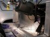
Curb Side Radiator Nose Coolant Fitting:
Last week I showed you the mock-up of a fitting we made out of PCV pipe. The radiator shop finished the fitting and it fits perfectly. Originally, I planed to run the hose from the radiator, through the back of the nose piece and to the passenger side coolant hard line. The problem was because of the location of the lift pump, the bend in the hose was to radical and kinked. The solution was the a hard line with three 90* bends and as I stated earlier, it worked great. (pic.#005)


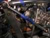
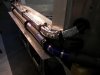
Passenger Side Coolant/Heater Lines Brackets:
George and I fabricated some rectangular shaped “U” flanged brackets that would allow me to stack the two coolant lines and the two heater hose in a nice neat cube. (pic. #001) I lined the inside of the brackets with some anti-abrasion adhesive rubber.


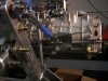
Passenger Side Coolant/Heater Lines:
I wrapped the the two coolant lines and the two heater hoses with some Dynamat heat reflective tape.(pic.#002 & #003)


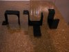
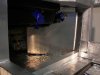
Passenger Side Foot Well Hose Cover:
We routed the four hoses through two 2.5” holes we drilled into the 45* angled-ed section of the passenger side foot well. This proposed two problems:

1) The hose was very visible, very ugly and would be difficult for the upholster to conceal!
  1. If involved in an accident, the heater hose could rupture and possibly scald the passengers legs (this actually happened to a very good family friend.).
Solution: I fabricated a cover that hides the hoses and can be easily carpeted over. (pic. #004)


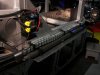
Driver's Side I.S.I.S Cover:
We mounted the two I.S.I.S electric control panels on the 45* angle portion of the street side driver's foot well. Although not as ugly as heater hoses, I wanted to conceal them so I fabricated a cover that would hide the control panels and could be easily carpeted over. For someone that didn't plan to do a lot of fabricating....I find myself doing a lot of fabricating!
Jim
 

Attachments

  • SL-C Build Progress-Week Ending 09-20-2013 005.jpg
    SL-C Build Progress-Week Ending 09-20-2013 005.jpg
    128.1 KB · Views: 407
  • SL-C Build Progress-Week Ending 09-20-2013 001.jpg
    SL-C Build Progress-Week Ending 09-20-2013 001.jpg
    157.6 KB · Views: 383
  • SL-C Build Progress-Week Ending 09-20-2013 002.jpg
    SL-C Build Progress-Week Ending 09-20-2013 002.jpg
    149.6 KB · Views: 427
  • SL-C Build Progress-Week Ending 09-20-2013 003.jpg
    SL-C Build Progress-Week Ending 09-20-2013 003.jpg
    123.3 KB · Views: 384
  • SL-C Build Progress-Week Ending 09-20-2013 004.jpg
    SL-C Build Progress-Week Ending 09-20-2013 004.jpg
    128.1 KB · Views: 361
A couple more pictures:
pic # 007 is the naked I.S.I.S control panels and pic. #006 is the covered I.S.I.S control panels.
Jim
 

Attachments

  • SL-C Build Progress-Week Ending 09-20-2013 007.jpg
    SL-C Build Progress-Week Ending 09-20-2013 007.jpg
    144.3 KB · Views: 389
  • SL-C Build Progress-Week Ending 09-20-2013 006.jpg
    SL-C Build Progress-Week Ending 09-20-2013 006.jpg
    162.2 KB · Views: 387
Jim - just a thought. If you have to change fuses or access the ISIS power module on that "B" pillar.... it's going to be a PITA.
 
Jim - just a thought. If you have to change fuses or access the ISIS power module on that "B" pillar.... it's going to be a PITA.

Agreed - that's a very bad location for it.


Thanks guys, I plan on mounting the fuse box on the rear bulk head around the corner from where I presently have the ISIS power cell installed. The fuse box will be fully accessible from the engine compartment.


I have seen where other builders have installed their ISIS P.C in the same location I choose, so I assumed that the frequency of accessing the unit is nil.


Where did you guys mount your rear P.C and could you please post a picture.


Thanks,
Jim
 
Alex, good to see you posting,:thumbsup: you have been absent for awhile and I missed your commentaries! Is your car up and running?


Jim
 
Alex, good to see you posting,:thumbsup: you have been absent for awhile and I missed your commentaries! Is your car up and running?

Jim

Finished a long time ago (at the beginning of the year). Although right now it sits crippled because my rear power cell (boy, can't imagine why I said that location would be a bad one :D ) blew and had to be replaced. On a side-note Jay has been great to deal with and warrantied it even though I bought it in 2009.

I would put it on the rear firewall or if you want a clean look, on one of the horizontal beams within easy reach.


Thanks Alex! So much for my theory that I would never have access the rear power cell. After reading your post, I turned off the football and am off to the garage to scout out a new location, but I'm running out of real estate.


Thanks again!
Jim
 
Jim it looks like you are doing a great job i love reading your posts can't wait to see pictures of you driving it , i hope to order my car soon
 
Fran, I just received my Graziano shifter and transaxel support braces today (thank you). Please look at the below photo (pic. #004 & #005) and tell me and the other Graziano builders that too are just receiving their parts if I installed the assembly as intended. :huh:


Thank you,
Jim
 

Attachments

  • SL-C Build-Week Ending 09-27-2013 004.jpg
    SL-C Build-Week Ending 09-27-2013 004.jpg
    157.5 KB · Views: 418
  • SL-C Build-Week Ending 09-27-2013 005.jpg
    SL-C Build-Week Ending 09-27-2013 005.jpg
    146.2 KB · Views: 426
The lower rod end fits on the other side of the trans bracket...the larger flat surface and yes the upper rod end is held on by the nyloc nut currently shown under it..
 
Back
Top