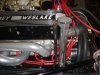
Keith's RCR GT40 Mk I Build

Keith

Lifetime Supporter
Yes, I copied Chuck and Ryan's work on the oil filter placement and the coolant recovery tank. Thank you Gentlemen!
I do not plan on using a coolant surge tank, only the recovery tank. I will post some photos next week after I have tested it to make sure the system will work properly. I have run the engine but not for long enough to make sure the cooling system will have the capacity to collect the expanded coolant at temperature and return it to the system when it cools down.
Keith
 

Rob

Lifetime Supporter
Excellent Keith. I like the execution of the cooler concept. Clean and well thought out. Nice work.....
 

Keith

Lifetime Supporter
Thank you all for the kind words.
I ran 1 and 1/2 gallons of fuel thru it Sarurday. The oil coolers worked great and had no leaks.
The radiator seems appropriately sized as I ran it in the shop on jack stands in 5th gear for over half an hour and it did not overheat (something I can not do with my big block Cobra as it will overhear in less than five if it is not moving). It appears that my cooling system works as intended so I will post photos this week.
I have been able to run it in all gears but reverse so I will have to make some adjustements to the shifter today (I wanted to make adjustments to it yesterday but the hot exhaust discouraged me).
I will have to make another video of the engine running as the first one I made when I started it for the first time shows me jumping back in surprise as it roars to life............
Keith
 

Rob

Lifetime Supporter
Great news Keith.
Looking forward to the vid and pics of the cooling system strategy.
 
I will have to make another video of the engine running as the first one I made when I started it for the first time shows me jumping back in surprise as it roars to life............
Keith


So what ?? This is not a casting show, we want the sound .-)))
 

Keith

Lifetime Supporter
Cooling System:
I took a somewhat different approach to the cooling system than others and I believe I have enough run time on the engine now to say that I believe it will have the required cooling capacity.
The thermostat housing is the "adjustable" housing from Summit that others here on the Forum have used (when you look at the photos please disregard my temporary coil hook up). I fabricated an aluminum tube assembly with a radiator cap bung (I machined my own but I have been told you can buy a weld on bung like this from Summit). It is connected to the thermostat housing with a Car Quest 20559 hose that was cut to length.
I machined a coolant tube 8.5 inches long for below the engine to connect the water pump hose, Car Quest 20842 cut to length, and a 45 degree bend cut from a Car Quest 22043 to connect the pipe comming from the center spine. The tube to connect the upright tube with the cap bung to the tube in the spine was cut to 11.5 inches and was also connected with bends cut from the Car Quest hose 22043 (this hose has a lot of bends in at and it will provide lots of opportunity to find the "right bend"). With a little work you can adjust the hoses on each end so that the two tubes run side by side down to the spine for a very "clean" look.
I did not use a "surge tank" just a two quart coolant recovery tank mounted to the transaxle like Chuck and Ryan used.
I was able to run the engine in the garage (with the cooling fans running) for over half an hour with no over heating. The coolant recovery tank got 2/3 full but after the engine was shut off and cooled down it was all was pulled back into the cooling system.
Keith
 

Attachments

  • GT40 051.jpg
    GT40 051.jpg
    142 KB · Views: 651
  • GT40 066.jpg
    GT40 066.jpg
    140.1 KB · Views: 670
  • GT40 239.jpg
    GT40 239.jpg
    148.6 KB · Views: 781
  • GT40 240.jpg
    GT40 240.jpg
    145.7 KB · Views: 822
  • GT40 236.jpg
    GT40 236.jpg
    139 KB · Views: 863

Chuck

Supporter
Keith:

Neat, clean design. I like that. Looks good. Avoiding the expansion tank takes one more potential issue out of play.
 
I dont want to sound negative, but I would wait until you have done some hard road miles to prove out that system . I can think of a couple of cars ( Non- GT40 ) with similar setups that required more 'header' volume than that to be safe over longer distances.
 
I think Jac Mac is right.Isolated /spot areas in the heads /block will reach higher temps and with greater flow taking the heat into the entire system,the temp rise may cause a bit more expansion.You would have to shut it down after some spirited driving and see if that, plus the rise from not having any more flow to the radiator after shutdown, causes enough additional expansion to warrant more capacity. A.J.
 
After engine gets hot and cools water level will be too low,air will be in top of engine.Also no bleed line from top of radiator to header tank , aerated water in radiator. regards Geoff
 

Keith

Lifetime Supporter
Thanks for the comments,
If the current two quart tank is not large enough my plan is to change to the four quart version that Canton makes (however, if you calculate the expansion of 4.5 gallons of water from 70F to 210F the two quart version should work). The real issue would be steam that expands at nearly 1000 to 1, even the smallest amount of coolant that turns into steam would overflow the tank.
If air/water vapor collects in the top of the radiator on a recurring basis my plan is to add a 3/8 inch stainless steel coolant tube to one of the fittings in the top of the radiator and route it to the "suction side" heater hose (I guess I will have to machine a fitting for this). Any of these changes will be easily accomplished even after the car is complete.
Time will tell........
Keith
 

Howard Jones

Supporter
Here's what has worked for me. I have run a 1/4" line from the top of the radiator (both sides Yed together) back to the header tank. I have also run a second line from the back of the intake manifold (again both sides Yed together) back to the header tank. My header tank ( aprox. 1.5 quarts) is as high in the car as possible on the bulkhead along side of the rear window (small vertical one) and the fill cap in within a inch of the top of the bodywork on the inside.

The header tank overflow line (1/4") runs back to the rear of the car where I have a 2 quart catch can to collect it and keep it off the track.

The header tank is fed from a bung welded to the top hard tubing that goes to the thermostat housing. That 1/2" line runs from there to the bottom of the header tank.

So the header tank has four lines running from or to it. One big one that feeds it hot coolant. Two that return air for the far ends of the cooling system and a overflow line from the high side of the fill cap.

It helps if you don't install the heater ( traps air) and I don't run a thermostat (increases turbulence in a already lengthily and complex system pulls the air out of the water). Just a flow volume restrictor plate in its place with a 5/8" hole in it.

This system allows the entire cooling system to continuously self bleed the air out. It works so well I simply fill it up and run it. No burping, overheating drama, or standing the car on end to bleed it, etc.
 

Keith

Lifetime Supporter
Electrical System:
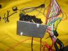
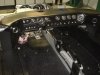
The electrical system was very straight forward and went together without any problems with the EZ harness supplied by RCR. It was a very time intensive project taking more than thirty hours and I still probably have a few hours of bundling wires and fastening them up under the dash after the roll cage is in and the dash is fastened into place. The good news is that everything worked as intended. There is no feeling like turning the key for the first time and having the engine burst into song.
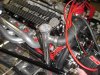
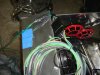
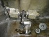
There are plenty of open circuits in the prewired fuse block for all the components I had. Even with the two fuel pumps, two fuel gauge senders, the transaxle oil pump, the Mallory Hyfire system and the trans temp/oil temp senders I still had three circuits left over.
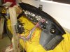
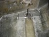
Per Fran's manual, I cut the wire ties apart and sorted the wires into four bundles, Front, Rear, Engine and Dash prior to starting the dash wiring. I cut an 1/8 inch aluminum plate to mount on the fuse block. I used this initally to screw to a 2x4 to hold it in position to wire the dash on the work bench then later I reversed it and flipped it over so it would mount to a 1.5 inch aluminum angle I bolted under the dash to the left of the steering shaft so that the fuse block would mount face down under the dash for ease of servicing. I tested each circuit while the dash was still on the work bench to make sure everything worked before I set it in the chassis.
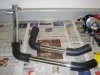
I made quick disconnects for the front and rear clips to make removal a little easier. These were made from a six pin "Weather Pack" connector for the powered circuits and a two pin "Weather Pack" connector for the ground circuits. This is the first time I have ever used this system and I really like it and will definately use them again.
I evacuated and charged the AC system and tested the AC and the heater to ensure there were would be no surprises later that would make me remove the dash. The blower fan is pretty powerful so I may take the grill off and drill a few holes into the duct work to put a little defroster air on the windshield, but I have not decided yet. The AC is plenty cool and the heat is way to hot so it should be "just right" in operation.
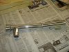
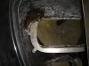
One last thing for you RCR builders; mount the brake light switch with the connectors facing DOWN. I had mounted it with the connectors up so the wires would be hidden. The steering rack makes it impossible to put the connector on if you do it that way.
Keith
 

Attachments

  • GT40 249.jpg
    GT40 249.jpg
    142.6 KB · Views: 615
  • GT40 241.jpg
    GT40 241.jpg
    150.2 KB · Views: 713
  • GT40 251.jpg
    GT40 251.jpg
    155.4 KB · Views: 631
  • GT40 244.jpg
    GT40 244.jpg
    156.9 KB · Views: 860
  • GT40 248.jpg
    GT40 248.jpg
    147.6 KB · Views: 657

Keith

Lifetime Supporter
Head Lamps:
My brother Ross came down from Wisconsin this week to help fit the body to the chassis. Ross really is not a "car guy", but that said, he is a very accomplished wood worker and boat builder. His skills with fiber glass were put to the test several times this week with excellent results. I hope to make several posts over the next few weeks detailing our efforts at the body fitting.

One of the jobs we tackled was fitting the head lamps. Fran supplied four identical metal brackets for the head lamps. Two were modified so that they would fit the flange on the front clip and could be glassed in place. The other two were attached to the head lamps with 10-32 hardware. One and a half inch long carrage bolts (1/4 - 20) were pressed into the the holes on the modified part and locked in place with jam nuts. Springs and nylock nuts finished off the assembly.
We cut the holes for the headlights using the dimensions provided by Chuck and Ryan in their build log (thanks again Guys!) as the measurements they used were perfect both from a measurement and visual perspective. We bonded the assemblies in place with a quick cure time epoxy then removed the head lamps and fiberglassed the brackets in place.

It appears to be a very functional setup with plenty of adjustment and we were very happy with the result.
 

Attachments

  • GT40 294.jpg
    GT40 294.jpg
    145.5 KB · Views: 537
  • GT40 293.jpg
    GT40 293.jpg
    143.8 KB · Views: 600
  • GT40 274.jpg
    GT40 274.jpg
    150.2 KB · Views: 575
  • GT40 275.jpg
    GT40 275.jpg
    154.6 KB · Views: 570
  • GT40 295.jpg
    GT40 295.jpg
    151.3 KB · Views: 595

Keith

Lifetime Supporter
Door Handles:
I wanted to have more support for the door handles than just the fiberglass "pocket" in the door so we decided to machine some "hinge blocks" from one inch square stock. The square stock was used so that there would be a lot of surface area for the fiberglass to grip and so that there would be a good flat surface area that could be machined to set the correct depth for the door handle in the door body. The blocks are 1 and 1/2 inches long with a 3/8 inch long shoulder 1/2 inch in diameter to clear the fiberglass recess in the door. This seemed to be good length as we could use a 4 1/2 inch long bolt and it would give us a more than an inch on the block for the fiberglass to bond to. We assembled the blocks with the door handle and a temporary bolt and held everything in place with duct tape from the outside of the door to establish the location. Ross then glassed the blocks in place with two layers of glass.
I machined a part to attach the door handle to the door latch from the one inch aluminum square tube I removed from the dash for the AC unit (1x1x1/8 aluminum angle could be used here but the tube was what I had). A 3/4 inch long by 5/8 diameter spacer was made to attach the handle to the angle, I drilled the hole in the door handle to 3/16 so I could use 10-32 hardware to attach it. It was assembled so that I could mark the location for the slot, I wanted to door to unlatch when the handle was out far enough to put my hand around it. I machined a 1/4 inch slot and used 1/4-20 stainless hardware (bolt, washers and a nylock nut) to attach it to the door latch (the part is two inches long with a one inch leg on the bottom and a 3/4 inch leg on the side with the slot, the slot location was different on each side so this measurement has to be made for each door individually). When assembled the door pops open when the handle is approximately 1 and 1/2 inches out of the pocket at the end of the handle.
I still have not found a spring that I like for holding the handle in place.....but I am sure I will find one soon.
Keith
 

Attachments

  • GT40 279.jpg
    GT40 279.jpg
    146.2 KB · Views: 574
  • GT40 277.jpg
    GT40 277.jpg
    153.1 KB · Views: 593
  • GT40 302.jpg
    GT40 302.jpg
    158.6 KB · Views: 527
  • GT40 301.jpg
    GT40 301.jpg
    143.8 KB · Views: 531
  • GT40 305.jpg
    GT40 305.jpg
    141.7 KB · Views: 664

Randy V

Moderator-Admin
Staff member
Admin
Lifetime Supporter
Nice work Keith! It looks like it will be a very solid setup!
 
Now Keith, that's really an excellent example of inguniety and forethought.
WELL DONE! I really love this forum. Everyone has some really cool ideas and solutions. I hope to contribute more as my SL-C build progresses beginning this week.
 
Back
Top