
You are using an out of date browser. It may not display this or other websites correctly.
You should upgrade or use an alternative browser.
You should upgrade or use an alternative browser.
Keith's RCR GT40 Mk I Build
- Thread starter K.Wilson
- Start date
Keith
Lifetime Supporter
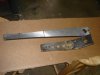
Front sway bar system:
The front sway bar system supplied by Fran is a very robust system that allows for a significant amount of customization to suit your needs. As my car will be used mostly on the street I reduced the diameter of the one inch bars by turning them down to .850 inch for the front and .750 for the rear. This type of splined bar is readily available so if I am not happy with my initial choices I will buy more and turn them to different diameters until I am happy with it.
I heated and bent the arms for the front so that they would line up with the lower control arm mount. In my case I used a 34 degree bend to get them where I wanted them. The next step was a weight reduction program on the milling machine taking approximately .200 inch off the top and the bottom of each arm, seven inches off the length, and some holes (1", 7/8", 3/4" and 5/8") to reduce the weight.
The bars, arms and bases for the rod ends went to the powder coater. I am pleased with the look of the final assembly. Time will tell if I guessed correctly on the bar diameters.
Keith
Attachments
Hi Keith,
great work, i have the same setup and thought about how to mount them.
These are just my thoughts , no personal experience:
generally GT40´s are known to have a tendency to understeer going into the turn.
Following the theory one would need a stiffer roll bar at the rear to load the rear tires more unevenly in order to provide less grip there and load the front tires more evenly to increase the grip there. I don´t know the length of your rear sway bar arms, but with the front sway bar mounted inside the chassis , the shortened sway bar arms and the bigger diameter of the bar itself, it seems likey that the front sway bar setup is much stiffer than the rear one. Have you done any calculation on that ?
I for my self decided to mount the front bar outside the chassis like Dean has done it and try to keep the maximum arm lenght both rear and front.
As said just the result of my thoughts, i´m shure there are more experienced ones that can chime in. So Dean, Ron McCall; Ron Earp; and any other one racing Gt40´s and using sway bars could you share your experience ( may be in the suspension section of this forum, to avoid a thread drift here)
Thanks
TOM
Keith
Lifetime Supporter
Tom,
I have not posted on the rear bar setup yet as I have the trans out fitting a new ring and pinion (I decided to replace both pinion shaft bearings since I was in there and they have not arrived yet). I will not do the final assembly on the rear sway bar system until the trans is back in.
The reason I made the rear bar smaller is that I made the sway bar arms an inch shorter in the rear and I mounted the block for the rod end 1 and 1/4 inch further outboard from the suspension point in the rear giving the rear a greater mechanical advantage than the front.
If I don't like the way it feels going into a turn my first change will be to move the rod ends further in toward the bar, the second will be to swap the bars front to rear, the third choice will be to get a new bar and see how a 1 inch bar feels in the rear.
Keith
Sounds like a plan. To be honest i haven´t spend any thought on the lever effect of the suspension mounting point at all. Great insight.
Are your bars the same lenght front and rear ?
When do you plan your first track experience ?
I have dont a excel calculation for sway bars, but is on my other lap top. Will post it tomorrow. Will be interessting to see the results from the different bars.
COuld you post the different mounting point leverage relations (in partitions from suspension mounting point to connecting rod mounting point to center of wheel, i hope this is the correct way to define the effects of the different leverages).
Would love to further discuss on this, are we going to put it in the suspension part of the forum or do we keep it here ( if you are interrested as well)
Thanks
TOM
Keith
Lifetime Supporter
Tom,
The front bar is a 33" bar and the rear is a 34". If I buy bars in the future I will buy the 34" bars and move the rod ends from outboard of the arms to inboard on the front to keep as close alignment of the rods as I can. That way I can interchange bars front to rear as required. I set it up that way with an eye on the future to make things as adjustable and interchangable as I could.
This is similar to the way I did my cobra. I had several bars 1", 7/8", 3/4", 5/8" and 9/16". After several trips to the "old airport" and a lot of swaps I settled on 1" in the front and 3/4 in the rear as my favorite (although I went an entire year with the 5/8 in the rear and have been tempted to switch back several times).
Keith
Guys,
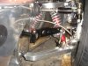
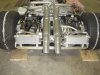
I did manage to get my RCR GT40 out on the track a couple of weeks ago. I hadn't had the time to fit the sway bars yet, but was surprised with how neutral the car was. In fact it had a touch of oversteer, which was quite unexpected.
I've only got a stock motor in the car at the moment, and that was down on hp, but found the car had really good corner speed, with plenty of grip. I didn't have a lot of static camber in and it had a fair bit of roll, but the slicks showed a reasonalby good temperature profile.
I will get the sway bars on in the next couple of months, but am expecting a fairly even rate front/rear.
I've attached some pictures so you can see the roll generated. 550lb springs front and rear.
Attachments


Good post guys, just about to embark on the front and rear sway bar fitment for my RCR40 and was one confused puppy. (http://www.gt40s.com/forum/240881-post23.html). I have one hollow and one solid so it looks to be a little different than yours.
Just a comment, I think the arms are from Speedway Engineering (Speedway Engineering's Sway Bar Arms / Hardware) and they have a note on their website regarding the steel arms:
They are available pre-bent and heat treated with a 3 ¼” offset ( see picture below ) or you can buy them unbent, bend them yourself and have them heat-treated locally.
Does anyone know what the heat treat specification is, or if its necessary?
Keith
Lifetime Supporter
Jason,
I would have to believe that the arms are way over designed/built for this application. In fact, I am looking for a shop that can put the splines in so I can fab some arms out of aluminum to get rid of the weight of the steel arms. (If I had a 1 inch bar with a splined end I could machine it into a broach to install the splines in an aluminum arm, something I may do when time permits).
If you look on the Speedway charts for a one inch bar the load is only 255 pounds at 5 degrees of twist on a 10 inch arm. Just guessing, I believe the arms could stand 10 to 20 times that without comming up to the yield point. The "weak link" in the system would be the 3/8 rod ends, they will yield long before the arms.
You can heat treat the arms if you like, however, even if they were annealed back to a "dead soft" condition, I believe they would still be several times stronger than any condition they would ever see in this application.
Keith
Keith
Lifetime Supporter
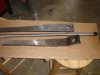
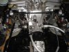
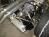
Rear Sway Bar System:
I mounted the rear sway bar below the exhaust and rearward of the cross brace. The arms were shortened to make a ten inch lever arm the same as the front (ten inches from the center of the sway bar to the center of the outboard rod end mounting hole). The arms went on a similar weight reduction program as the fronts prior to powder coating. I fabricated mounts for the pillow blocks from 1/2 inch steel stock and mounted them utilizing two of the 1/2 inch Grade 8 bolts for the cross brace. The actuator rods were made from two twelve inch long pieces of 5/8 alloy (6061). As with the fronts I drilled and tapped the pillow blocks for grease fittings. As soon as I can get access to some race car scales I plan on doing some sway bar "rate" measurements.
I mounted the rear sway bar below the exhaust and rearward of the cross brace. The arms were shortened to make a ten inch lever arm the same as the front (ten inches from the center of the sway bar to the center of the outboard rod end mounting hole). The arms went on a similar weight reduction program as the fronts prior to powder coating. I fabricated mounts for the pillow blocks from 1/2 inch steel stock and mounted them utilizing two of the 1/2 inch Grade 8 bolts for the cross brace. The actuator rods were made from two twelve inch long pieces of 5/8 alloy (6061). As with the fronts I drilled and tapped the pillow blocks for grease fittings. As soon as I can get access to some race car scales I plan on doing some sway bar "rate" measurements.
Attachments
Last edited:
Keith
Lifetime Supporter
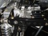
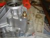
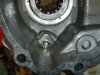
Transaxle oil temp gauge:
I installed an oil temp gauge in the dash and my intent was to use it to measure both engine oil temp and transaxle oil temp with a selector switch. While I had the transaxle out to replace the ring and pinion (moved it up to a 3.22 to 1 in a 016-5N) I looked for a place to install the oil temp sensor. Since the "fifth gear" indicator switch would not be used in my application it seemed like a good spot to mount the oil temp sending unit. I faced the end in the lathe and drilled and tapped it to 1/2 NF. I hope it works as good as it looks........
Keith
Attachments
I have been thinking about doing the ring and pinion swap. Did you do the swap or did you need to hire the work out?
Jonathan,
I also run the 5N with a 3.22 ring gear. The instructions were quite complete but i decided to farm the work out before I messed things up. I think it cost me around $350.00 at a local transmission shop.
Peter
I also run the 5N with a 3.22 ring gear. The instructions were quite complete but i decided to farm the work out before I messed things up. I think it cost me around $350.00 at a local transmission shop.
Peter
Keith
Lifetime Supporter
Jonathan,
Yes, I did it myself and it is relatively straight forward. The cross piece on my 12 ton press was not large enough to accept the pinion shaft to press off the gears/bearings so I had a friend with a 20 ton press pull the parts off the old pinion shaft (thank you Rick). We heated the gears/bearings on a electric "hot plate" so they would just slide on the new pinion shaft.
The only real difficult part of the replacement is the race for the forward pinion bearing. As the pinion gear for the 3.22 is much larger than the 4.11 it will not pass through the race; so the race has to be assembled on the pinion shaft first then it is pressed into the case as an assembly with the pinion shaft and the rest of the gear case. Getting everything lined up "in the blind" so the race can be pressed into the case along with the bearing shims is difficult at best.
I hope to start the engine and test it out this weekend.........
Keith
Keith
Lifetime Supporter
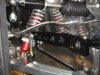
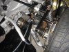
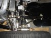
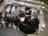
Engine oil cooler and transaxle oil cooler:
I fabricated two aluminum brackets for the oil coolers from 1/4 aluminum plate stock and mounted them so that they would be centered in the outboard openings in the rear clip. The engine block adapter and the remote oil filter adapter were purchased from Canton and I really can't say enough about the quality and the look of their product. They really look great! I fabricated fittings for the two "extra ports" in the remote oil filter housing, one on the inlet side to hold the oil temp sensor and the second for an oil light sending unit (I have an oil pressure gauge as well as a low oil pressure indicator light). I fabricated the lines with Jegs polished aluminum AN fittings to keep with the "black and polished" look.
While I had the transaxle out I machined an adapter so that I could fit an AN fitting to the drain plug hole in the transaxle. I drilled and tapped a boss in the casting on the right side just ahead of the trans mount holes for an oil return. The pump for the transaxle oil is a Tilton unit with a built in check valve to keep the oil in the cooler from draining back into the transaxle when the pump is off.
If all goes well this weekend I hope to be able to start the engine and test it.
Keith
Attachments
perfect work as always
What is the tank in front of the trans oil cooler, it is an overflowtank ?
TOM
Tom: That would be the recovery tank. Likely a Canton two quart unit #80-201. The expansion tank is, I assume, on the firewall above the level of the thermostat. One could add a third tank, an overflow tank, to the out put of the recovery tank if necessary, but with the recovery tank it should not likely be needed.
Last edited:
Similar threads
- Replies
- 0
- Views
- 551