Ken's SLC build thread

It's important to mention the fact that the C6 Corvette gauge cluster can only be used if you are using a BCM (body control module). I didn't purchase the ISIS wiring harness. My wiring is basically taken from a C6 Vette. All the "not used" features are depinned from the harness. I built the engine harness the same way.

Since you are using the BCM are you going to control the alternator with it, this will reduce drag by the alternator when the battery is fully charged and over charging? Depending on the system you may need to get other parts from GM to make that work. The alternator control has been on most cars since the 90's for better mileage.

If someone were to put the battery in the cabin this would also help.

If you are interested in Alternator control this is MegaSquirt's forum site. For those wondering MegaSquirt 3 is an engine control for EFI mostly for racers and DIY that do not need meet the rules for the street. It does go into a lot of detail.

I didn't want any galvanic corrosion interfering with the connections.

You also should use Noalox Anti-Oxidant Compound for reducing galvanic corrosion on any mechanical connections running electricity though it. It can be purchased at Home Depot or electrical supply house.

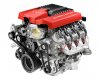
Look's great and see why it wins awards!!
 
Last edited:

Ken Roberts

Supporter
The car is wired very similar to the C6 Corvette. I've used as much of the interior and all of the engine wiring harnesses as possible.


I've studied the Pontiac G8 GXP wiring as well. It has far more control over the alternator charging/output then the C6 Corvettes. I wasn't able to incorporate it however as I want to run the C6 Corvette modified tune. I am however using the G8 GXP alternator though.

I'll look into that product. Thanks for the tip. I'll see if I can find it up hear in our Canadian Home Depots.
 
As I understand it the alternator is controlled by the BMC and the EMC just provides connections and inputs. The provider may have just removed the connections. I hope the gauges you need still work, if they don't you may have to send the EMC back. If you have to send it back you then ask about the alternator. The connections on GM's are all the same just the output (AMPs) varied. That is what I read in GM's paper on alternator control it may have changed since then.

The Noalox is on Home Depots web site I would get the six digit SKU# so the Associate can find it easier or you may mail order it to the store, from the web site, if they don't carry it.
 
Last edited:
Regarding alternators GM has made a design change for some of the later years. The new ones appear to be triggered by a PWM signal and you can not mix and match. This is important for the folks using the CTV alternator.

What they were saying in MegaSquirt forum was the the were using PWM signal, it could be the now use different freq to reduce noise interference.

It is something to think about when you do as Ken did, just make sure you have all the correct components.

Thanks for the update Mark.

If you do wiring in your house that is what the Noalox is designed for.
 
Last edited:
I have been playing around with different crimping and soldering techniques for the main power and ground cable lugs. I just wasn't happy with the soldering methods. I bit the bullet and bought a professional style crimper that swags the lug on. It takes a bit of practise to perfect the technique. I purchased a few extra lugs to practise with.


If you want another crazy tip. On crimps that you do yourself you can use Synthetic Rubber Coating dip like Plasti Dip or Dip and Grip after covering the electrical connection with masking tape. This will make sure they are water-tight.

Especially if you run out of heat shrinks!!
 

Ken Roberts

Supporter
For anyone interested in a Racelogic traction control system or just buying spare wheel sensors for it here is a tip. I just purchased a second set of sensors (IFM IE5238) from a company on eBay for $225 shipped (for a set of 4). That's half what they usually sell for. Racelogic sells them for $414.

They have a few more listed. You can pm me for a link or just search the part number.
 
"If you want another crazy tip. On crimps that you do yourself you can use Synthetic Rubber Coating dip like Plasti Dip or Dip and Grip after covering the electrical connection with masking tape. This will make sure they are water-tight.

Especially if you run out of heat shrinks!!"

You can also use marine grade crimps, bus bars and heat shrink (available at marine supply stores like West Marine)
 

Ken Roberts

Supporter
I'm back on track after spending most of the winter months building another complete wiring harness based on the C6 Corvette architecture for a possible GT-R purchase in the future.

I recently found a alternative/cheap GM made power steering delete bracket and pulley system. This type of bracket/pulley bolts to the front of the drivers side cylinder head. GM used these parts on the 2014 Camaro LSA engine and Camaro Z28 LS7 engine. These cars had electrically assisted power steering (EPS) and didn't come with a traditional engine mounted PS pump. They both have the same belt wrap (distance to block) as the Corvette.

Here are the part numbers:
bracket-#12641124
pulley-12629519
bolts-11518633 (3 required)

Here are some pictures
 

Attachments

  • 6_2-LSA_zpsn5uksadg.jpg
    6_2-LSA_zpsn5uksadg.jpg
    109 KB · Views: 300
  • 2014-camaro-z-28-launched-with-70l-ls7-engine-photo-gallery-medium_11_zpswgpamwxf.jpg
    2014-camaro-z-28-launched-with-70l-ls7-engine-photo-gallery-medium_11_zpswgpamwxf.jpg
    73.5 KB · Views: 283
Last edited:

Ken Roberts

Supporter
I decided to add a fuel pump inertia switch. This will be installed close to the drivers seat . It gets connected to the ground side of the fuel pump relay. I chose this model due to it being used extensively by OEM manufacturers. They cost around $50 to $75. Here are some part numbers for it:

AC Delco- #D1876D
Standard Motor Products-#FV-7
 

Attachments

  • 002_zpsqeh8kl1c.jpg
    002_zpsqeh8kl1c.jpg
    51.1 KB · Views: 309
Last edited:

Ken Roberts

Supporter
I finished the final version of the pedal assembly. I added a second rheostat. This one is mounted to the clutch pedal. This one will control the clutch switch (engine start) and cruise (disengagement).

The second picture shows the Lingenfelter CTAP-001 box. It learns the voltage swing from the rheostat (0 to 5volt range) when you press the pedal and then allows you to program in where in the arc you want the switches to activate. The engine start switch is "normally open" and the cruise disengagement is "normally closed". Both types of switching are available with this unit. The switching is done with the relays I have mounted next to it.

This box can also be used for the throttle position. It could be used to disengage the A/C under full throttle or to activate/deactivate a nitrous system.
 

Attachments

  • IMG_1513.JPG
    IMG_1513.JPG
    139.4 KB · Views: 301
  • 007_zps0vgb9af6.jpg
    007_zps0vgb9af6.jpg
    72.5 KB · Views: 304
Last edited:

Ken Roberts

Supporter
With safety in mind I elected to completely remove both the tilt and telescopic motors from the steering column. The telescopic motor is useless in my opinion anyways. The steering wheel needs to be completely extended in order for the tilt function to work. This is the only position that will allow the wheel to tilt without obstruction (at least in my build).

The picture in this post shows how I can still use the tilt feature manually. The telescopic feature was locked out with the use of a threaded rod. It was carefully designed though so that the column can still collapse as designed in a collision. I modified the cable to include the use of a wheel at the end so I can adjust the position manually. The cable can now be positioned high and away from your feet. I bought a small aluminum wheel from McMaster Carr and tapped/threaded two set screws in the sides of it. Here is the part number for it:

#6047K12 McMaster-Carr
 

Attachments

  • 004_zpswawsxjpz.jpg
    004_zpswawsxjpz.jpg
    54.7 KB · Views: 294
Last edited:

Ken Roberts

Supporter
Two additions to the Ricardo transaxle oil cooler install are in final design currently. The first picture shows the Spal fan that will be installed behind the Setrab 625 oil cooler. The second picture shows the Improved Racing model #FSM-165 thermostat that will be installed in the circuit to prevent oil from reaching the cooler until the designed 165 oil temperature is exceeded.
 

Attachments

  • 004_zpsxgml25ir.jpg
    004_zpsxgml25ir.jpg
    120.9 KB · Views: 278
  • 003_zpsysr1nlwc.jpg
    003_zpsysr1nlwc.jpg
    127.4 KB · Views: 319
Last edited:
Ken,
I had not checked into your build for a while, some really sophisticated OEM level sensor work going on up there. I like that inertia cut off switch too.

Something tells me you are very comfortable with electrical systems.....
 

Ken Roberts

Supporter
Thanks Mesa. It all started with our first cars (me and my brother). He bought a Triumph TR7 and I had a Fiat X19. We were always fixing the electrical gremlins that would pop up occasionally. I got my first taste for a mid engine car back then. I'll never forget the superior handling of that layout.
 
Ken... Everything you do is nothing but first class. Could you post some more pics of your sweet peddle assembly. Maybe form a couple more angles. That is a really nice job and I look forward to the rest of your build. Thanks for all post. Once again nice job Sir....:thumbsup:
 
Ken... Everything you do is nothing but first class. Could you post some more pics of your sweet peddle assembly. Maybe form a couple more angles. That is a really nice job and I look forward to the rest of your build. Thanks for all post. Once again nice job Sir....:thumbsup:

Ditto...

Ken- your mods are very well thought out and executed. Thanks for sharing.
 

Ken Roberts

Supporter
Thanks for the kind words Joe and Ricardo. Here are a few extra shots of the pedal assembly. I kept adding on to it in stages until I was satisfied with it's strength to weight ratio. I want consistent voltage readings. Corvette, CTS V and Camaros use these rheostat type of switches. The clutch rheostat reads the opposite of the brake rheostat. One has a rising voltage signal while the other has a falling voltage signal.
 

Attachments

  • IMG_1513.JPG
    IMG_1513.JPG
    139.4 KB · Views: 268
  • IMG_1514.JPG
    IMG_1514.JPG
    136.6 KB · Views: 243
  • IMG_1515.JPG
    IMG_1515.JPG
    138.5 KB · Views: 291
Last edited:
Back
Top