Back to the hubs again. Can the speed transducer be removed from the SKF hub and then saved for use by another. I don't need the anti lock brake system.
Back to the hubs again. Can the speed transducer be removed from the SKF hub and then saved for use by another. I don't need the anti lock brake system.
I'm afraid not Howard. It's not serviceable. You would just cut the wire leads off at the hub.
I know a guy selling brand new SKF X Tracker ZR1 hubs for $275 each if you are interested Howard. They have the active ABS sensors so if you are planning on cutting the wires off these would be a little bit cheaper.
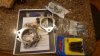
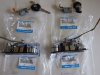
To help clear up some confusion. Here is a picture of the adapters needed for the conversion of the SKF X Tracker hubs to fit our uprights. Everything in the picture is included. They are chromoly steel. They cost about $475 shipped
Our SLC rear hubs cannot be upgraded. The C4 rear hubs that are used on our cars have a 27 spline axle stub shaft. The C6 Corvette hubs have a slightly different bolt pattern and they take either a 30 spline stub shaft (1997-2008) or a 33 spline stub shaft (2009-2013).
Thanks a lot for that! I will certainly need to do a upgrade. The fronts are already showing a bit of play in them after about 200 track miles. Not at the point that would lead to emanate failure, but I would call the owners attention to them if I did the tech inspection and want to see the car the next morning for a two day event.
Ken could you send me a Ph# and time to call for you via PM. I would like to talk a bit more about this. Thanks, Howard
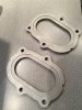
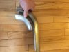
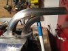
Start with a good set of flanges. I like to use original flanges if possible. The only way to acquire them is to buy the mating cat pipes off the C6 Z06 Corvettes. I buy them for the catalytic converters as well due to our emission laws in Canada. If that isn't possible then you can buy them in the following link but they won't have the step built into them as original. A pair of them in 3/8" stainless is $152.
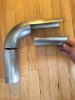
The ends can be squeezed slightly in a vise so they fit in the stock flanges. Next is to tack weld everything together.
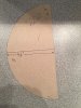
Once that is accomplished the flat sections need to be fabricated. Trace the openings out on some paper and then transfer the paper cutout to some flat stainless sheet and cut them out.
If you want to make them on a budget then the flanges and pipes can be purchased in regular steel instead. Stainless has better heat retention and will hold up longer but if you are going to ceramic coat them then perhaps it's not for you.
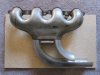
The same process can be done if you want to save some weight. Carefully (with a reciprocating saw) cut the flanges off the stock manifolds and then weld the modified pipes directly to the manifolds.
In this case you can recoup some of your cost by dressing up the cut off flanges and selling them. That's what I did.
After tacking it all together I have a 5/8" steel plate that I bolt the flange to. This helps prevent it from warping while being welded. It acts as a heat sink as well.
Warping of the flange could allow an exhaust leak which will screw with the oxygen sensor reading.
These plates let you R&R the engine with the intake manifold in place. You can't go wrong for $50. My used Kent Moore plates were over twice that price!
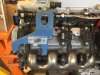
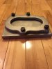
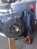
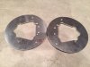
Building the cooling duct plates for the rotors. This becomes easier due to the adapter plate having provisions for it. Next up is to carefully cut holes in one side for attachment of the hose. I purchased a second set of adapters for the GT-R build so I am making two sets of plates.
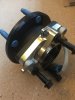
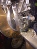
This picture shows the backside of the plate once installed. This is the open area where the hole will be cut out and tube welded on and mounted to the side of the upright. The picture also shows the wheel sensor wiring connector mounts made for the traction control. The small bracket on the left side is to ty-wrap the wire loom in place and the larger bracket on the right holds the harness connector.
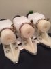
Here is an idea for builders who don't want use rubber hose for the lines from the reservoirs to the master cylinders. The kits comes with Wilwood brand components now instead of Tilton like shown in the following picture but the theory is still the same.
I carefully cut the hose barbs completely off the bottom of the reservoirs. The surface is then made smooth by carefully using a stationary belt sander. The holes are then opened up to 25/64" to receive a stainless 4AN fitting. The fitting is installed from the bottom and held in place internally with a stainless AN 12pt nut. (Cheaper aluminum fittings can be used as well)
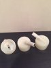
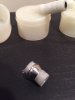
The tip of the hose barb is cut off the plastic master cylinder reservoir fill port. The remaining hole is slightly enlarged to receive a small length of 1/4" stainless tube to act as a reinforcement. I then install a Swaglok compression 4AN fitting to the barb after hand sanding the tube down to the correct diameter to receive the fitting. I did a test fit with a spare one I had purchased and it was very robust. You can see it in the third picture. The compression fitting worked perfectly.
I'll update this post once I receive and install the fittings to show the end result.
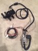
I'm selling my heater by pass set up for use with LS engines(never used). This is the Old Air Products 50-1555. I converted this control to be used by a toggle on/off switch instead of a rotary switch. Mine can also be used with no switch at all for stealth operation. You would just tap in to the "AC on" power supply. When you turn the Air conditioning on this would automatically close the valve to by pass the heater core. One less switch to install. $80 plus shipping. SOLD