Hi Guys....Isn't the internet a wonderful thing, I can sit on the other side of the world and by stuff at home and when I get home its there waiting for me. My wife is not all that shore about how good it is, My latest purchase for my scratch built was the Balsa wood to laminate the bulkheads and cocpit side walls, I was going to use Ceder but after finding a supplier who can do the Balsa it made sence to use it and I also bought a fuelinjection setup.

You are using an out of date browser. It may not display this or other websites correctly.
You should upgrade or use an alternative browser.
You should upgrade or use an alternative browser.
M20 Dreaming
- Thread starter leonmac
- Start date
![98793527[1].jpg](/data/attachments/30/30616-5d35610b8b6bbc06832d9ca04529e07f.jpg?hash=XTVhC4trvA)
![98793533[1].jpg](/data/attachments/30/30617-3c759b434234fd08d6b6303c81498988.jpg?hash=PHWbQ0I0_Q)
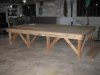
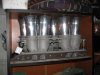
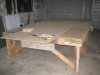
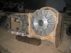
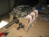
Back home again and wasting no time. I spent the first few days building my chassis table. (Mental note to self) When building large item that needs to be turned over in restricked height make sure to measure said height!!! you guessed it, Made my table and decided to make it 2.4m wide to save cutting on the sheets and and then thought OH!! Shoot!! How high is the roof??? answer, 2.35m !! so I had to do a little mod and now its 2.2m wide and all is good. The casters had not done my uprights, so I had a wee word in their ear and they have now done them and I will pick them up tomorrow. I have started the mould for the gearbox housing and will make that a priority this time home and also to get the hubs and brakes mounted on the uprights. The fuel injection unit I bought was at home waiting and I'm well pleased with the condition of it. To answer a question Jac mac had, The spline count is 31 and the axle is 1 1/4" Not being a Ford man, how does that compare to a 9" axle??. My plan off attack now is to mark out the wheel base, track, engine position and tub layout on the table. I have a dummy block and I will fab up the rear bulkhead and engine mount and work forward with the tub, I will make brackets to hold the hubs and upright's in the right position for track/wheel base and then build the "A"arms and trailing arms etc to suit. I have put a couple of pics of the table and Injection in and will post photos of the uprights in couple of days. Cheers Leonmac.
Attachments
Leon,
That's a Monster of a table.
Dave
That's a Monster of a table.
Dave
Terry Oxandale
Skinny Man
Thanks for the pics Leon. Looking forward to watching this build.
ox
ox
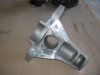
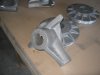
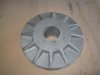
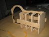
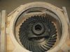
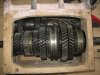
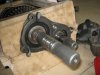
Hi Guys.......I think I have the worlds most robust Ping Pong Table. Picked up the uprights from the casters this morning and quite pleased with the product. Obviously they are in their Raw state and now need to be machined, which I will get onto in the next day or so. "AS IS" the fronts are 4kg but one of the arms has to be removed from each one and the centre turned out to take the bearings and I have to add the bracket for the brake calliper. The rear is 9kg "as is" once again the centre has to be turned out a lot, I chose at this point to leave them solid rather than hollow core for 2 reasons. (1) the extra weight is 2kg and as this is a classic and not F1 I can live with the extra weight (2) the cost and work required to make floating cores. I may however do some hollow core uprights in the future. The side plate's for the trans axle are also way over size to allow me to adjust them to suit the final set up of the Trans Casing which I'm currently working on and would like to have at the mock up stage before going back to work, I also picked up an engine block to start setting up on the table. Took some photos of the castings in the raw state and will post the finished one's soon (I hope)
Terry, I have been following your build with interest and good to see how your suspension set up is going. You guys in the states have an advantage with being able to get parts from late model Vette's etc for good money, here in NZ that stuff is like Rocking Horse Pooo and and not cheap, Keep up the good work and if I can help you or you me, I look forward to your ideas. Cheers leonmac.
Terry, I have been following your build with interest and good to see how your suspension set up is going. You guys in the states have an advantage with being able to get parts from late model Vette's etc for good money, here in NZ that stuff is like Rocking Horse Pooo and and not cheap, Keep up the good work and if I can help you or you me, I look forward to your ideas. Cheers leonmac.
Attachments
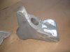
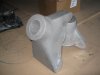
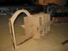
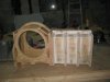
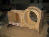
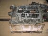
Hi......I have been and done some intial machine work on 1 of the front uprights But then had to go and have Knee surgery and that has stopped me from driving so I can't get to my machine shop. So I have started to make the mould for my Trans axle casing. To make the casting process less complicated, I am doing a split case design. I'm driving through the Lay shaft and then via QC gears to a third shaft for the pinion. The main reasson for this is because the LSD centre is large and I can't get a desent size spigot shaft under it, so running the third shaft allows for QC gears and also gives the clearance needed. I have posted a couple of pics of the skeleton of the casing and tomorrow will continue with 8mm ply for the flat surface's. I will post pics as it progresses. Cheers Leonmac
Attachments
Howard Jones
Supporter

Hi Russell, good to hear from you. Anything you have on the M8F suspension would be of help as the M20 basicaly used the M8F uprights and Layout with a few changes, Longer wheelbase and slightly wider track. The tubs are totally different as the 20 had side mounted radiators and the engine and driver were mounted 8.5" further foward. I do have some stuff on the 8F but will happerly take any help offered. [email protected] is my address, look forward to hearing from you. Jac Mac, I guess you noticed the burn marks on custom wood. I will be carefull as you say the stuff smokes real easy when using the skill saw but seems fine with the Jig saw, although I have killed the cheap Jigsaw and my mate who is a Builder has lent me a good quality one. I have made a lot more progress from the other day and will have some more pics soon. How are you going with your Transaxle ??? I'm real keen to see some more detail, I will set all the gear stack and Diff in the wood mould and actually make it a working unit before I go to the casting stage, I only have 10 days before I go back to work so probably not this time. Cheers Leonmac
Hi Leon, yes I think its the resin they use to manufacture the stuff with, you will have similar problems if you try to use a hole saw etc as well, the stuff made down here by what was Raynier/now Dong Wha is nowhere near as good as the grades we used to be able to get from the old NZFP plants etc, thats why I gave the whole setup a coat of epoxy resin as anywhere the core was exposed was tending to split.l I had quite a bit of that NZFP grade over from when I built my Daytona buck which I have virtually used up now. Would love to be able to get a large slab of the 'Necuron' that is being used on the F3L project elsewhere on the site, but looks like closest source is Germany.
Hi Jac, The custom wood where its edge is exposed soaks up the paint etc so I was wondering what to put on it when I finish and ready to paint, I was thinking of painting and then coverig with Polyurathene which should give it a smooth shiny finsh. also there will be a resonable cover of Bog over most of it so that should help. The moulds for the uprights were bog and I just used Satin finish black spraycoat and they were just fine. What are your thoughts. Cheers Leon
Hi Jac, The custom wood where its edge is exposed soaks up the paint etc so I was wondering what to put on it when I finish and ready to paint, I was thinking of painting and then coverig with Polyurathene which should give it a smooth shiny finsh. also there will be a resonable cover of Bog over most of it so that should help. The moulds for the uprights were bog and I just used Satin finish black spraycoat and they were just fine. What are your thoughts. Cheers Leon
Hi Leon
MDF have different density. I noticed that the lower density is very hard to control, sometimes it will break off, that is why I used the high density MDF. Using MDF primer to seal the surface, it will save you alot of time :thumbsup:for sanding and finished with grey acrylic primer.
Hope this will help you
Lim
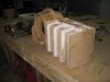
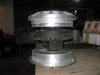
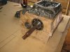
Hi Guys, Some more progress this week on the Trans axle. I have done some rough work and set the diff in the side plates and mocked it up in the wooden mockup. the original idea was to make the whole thing in one piece but this has changed to make it easier for the location of the bearings and retainers. as you can see from the pics I'm also using the original Nissan selecter and forks, again to make life easier. The next step is to locate the main shaft and gear stack as well as the ley shaft then the pinion shaft can be setup and the drop gears worked out and of course the spigot shaft. Once I have the whole unit set up and it will work and shift gears etc then I will have the Alloy casing made up and then to the very precise job of machining!!! Have a look and any ideas would be greatly appreciated. Cheers Leon
Attachments
-
 McLaren Project 018.jpg31 KB · Views: 884
 -
 McLaren Project 019.jpg31.5 KB · Views: 818
 -
 McLaren Project 020.jpg32.5 KB · Views: 860
 -
 McLaren Project 021.jpg44.3 KB · Views: 872
 -
 McLaren Project 022.jpg27.3 KB · Views: 834
 -
 McLaren Project 023.jpg35 KB · Views: 785
 -
 McLaren Project 024.jpg37.6 KB · Views: 961
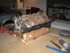
Hi, the last few days have been spent fitting the main and Ley shafts for clearance's and rotation. after fitting the shafts I checked the centres by using the original bearin retainers and to my delight they were perfect, suprising concidering the bearing loctions were cut with a jigsaw. Next was to fit the selector and see if it would select gears which it does, so far so good. Next is to cut of the long shaft sticking out the back but leaving the spline at the bearing which will carry the QC gear that will drive the pinion shaft (not yet fitted) the short shaft on the ley shaft will drive the oil pump. At the front the exsisting spigot shaft will be removed and a new one will drive throught the ley shaft, the shaft will have a spline cut on the end under the current bush that the bearing runs on. The new spigot will then press onto the spline and carry the bearing. The diff housing will have the suspension pickups cast as part of it and I'm making it as per LG 500/600 spec for the bell housing and suspension pickups. Please feel free to comment or criticise my methods or design as all the help I can get from the forum will be apreciated, Just don't say it can't be done, as you probably have guessed, Kiwi's don't understand can't. Cheers Leonmac.
Hi Leon
What gearset are you planing on using.
Jim
What gearset are you planing on using.
Jim
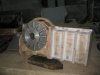
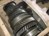
Hi Jim, the gearset is from a Nissan patrol as is pretty much the whole drive train, Diff , CVs, half shafts, hubs. the reason is simple. (1) I had it all in my garage from my off roader days. (2) I know its strong as I ran a 600HP chevy in front off it and it never broke. It is heavy as the shafts, gears and bearings are large, the diffs are 10" crown wheels with 31 spline axles. I tryed to post some more Photos earlier but had problems down loading so I will try again now. Cheers Leonmac
Attachments
Leon
It will be strong alright ,good on you.
Your ratios will be a bit ordinary I would imagine but you can sort that by having gears made.
I will be watching you and Jac mac with your transaxle projects.
jim
It will be strong alright ,good on you.
Your ratios will be a bit ordinary I would imagine but you can sort that by having gears made.
I will be watching you and Jac mac with your transaxle projects.
jim
Jim, yes the ratio's are a bit wide as std but as you say this can be overcome with custom gear sets. My aim is to make it all work first and long term I'm planning Better ratio's and Dog Engaugement, I also think that the wide ratio's I will have to start will be offset by the the fact that a 509 or 565 cu in Chev will be in front of it and the torque will take care of a lot of the short fall. FYI, the ratio's are 1st 2.87 2nd 1.65 3rd 0.95 and 4th 0.62 Diff is 4.1. I will probably change the 4th gear from the get go as it is too high and I want around 0.75, with 27" tires this would give about 205mph at 7000rpm, the 0.62 is about 225mph. The other thing to note is that with the QC gears that I will have running the pinion shaft make these ratio's subject to easy change although the spread obviously doesn't change. The ratio's I have given are with the 15% OD that I already have QC gears for. Hope you find this of interest, Cheers Leonmac.
Last edited:
Similar threads
- Replies
- 7
- Views
- 878