McLaren M20#73

Thanks guys..
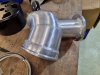
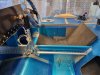
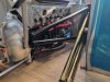
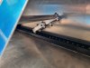
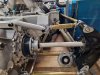
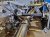
Nearly completed the Intake pipe. Just stepped it from 3 to 4”. Mounted the Race Valve and the Intake Air Temp sensor and bung.
I still find it challenging welding thin contaminated aluminium pipe, but it came out ok. Might paint it stipple black.

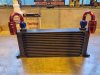
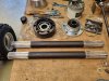
I priced up 4 an fittings for the trans cooler I had here in NZ. It worked out cheaper to buy a new 16 row radiator, 20ft of pipe and 10 x AN8 fittings thru Amazon including freight. No wonder I import so much. we just get rogered here.

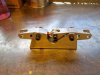
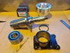
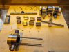
Moved the water pump return to the top boss and welded up the front facing inlet…. for better routing of water pipes.
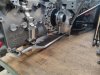
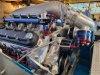
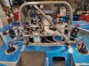
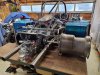
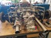
Nearly ready to put the motor back in the car.

Question. I can see the best way to mount the trans radiator is with the 180 deg fittings from the top so it bleeds out the air, but is it ok to feed and pull the oil from the bottom of the radiator. Will it get an air block?? I have space constraints.
Andrew.
 

Attachments

  • M20 intake.jpg
    M20 intake.jpg
    335.8 KB · Views: 546
  • M20 trans rad.jpg
    M20 trans rad.jpg
    281.3 KB · Views: 549
All the original cars have them plumbed in the bottom so I don't see that being an issue, I'm back on deck so will courier the flanges on Monday. Cheers Leon.
 
what are you doing to do with the heater loop on the water pump? I understand that flow through that loop has some effect on initial opening of the thermostat.
 
Tom that question got my curiosity going. I pulled the water pump off to have a closer look. This is my first LS based motor.
Water appears to flow the opposite direction than I thought.
Water is pumped from the reverse direction water pump to the engine rectangle ports in the block. Hot water then comes out the top round motor ports and enters the water pump again exiting out the top water pump outlet to the radiator, then returning to the thermostat housing inlet port.
When the thermostat is shut, water is in a closed loop and pushes past a spring loaded block off cup on the end of the thermostat. As the thermostat opens as temperature increases, water can start flowing out the top outlet, thru the radiators and return to the thermostat housing port.
I maybe wrong.
 

Attachments

  • 20211014_165430.jpg
    20211014_165430.jpg
    506.6 KB · Views: 425
My outer drive flanges arrived. Remade to fit the larger 934 CV's. Quite tight in the suspension uprights but should be fine.
Also got my rims back from the engineers. A bit of work now to reassemble and make sure they're running true.
Also going to shorten the
mount tube for the BOV race valve. Its a bit long.
Andrew
 

Attachments

  • 20211014_165503.jpg
    20211014_165503.jpg
    505.4 KB · Views: 411
  • 20211014_165604.jpg
    20211014_165604.jpg
    317.8 KB · Views: 446

Howard Jones

Supporter
With the fittings on top, the radiator will not drain when you drain the system in the future. But you knew that. The other thing is air is usually traped in the plenums on the top and bottom of engine coolant radiators or at the top of the side if they are on the sides. The oil type you have generally don't have much of a problem trapping air in them so if you have a choice, place them fittings down. I have my engine oil cooler placed fittings down and see no problems (delay to build pressure caused by an air bubble in the cooler) with oil pressure on startup.

The one thing that you might consider is if you plan to not run the transaxle oil pump all the time then the radiator oil capacity will tend to slightly overfill the transaxle if it is mounted above the gearbox (cooler pump and lines volume). I personally don't think this is a short-term problem as in warm-up laps. Having all the oil in the gearbox as it warms up will at least warm it all up at once.

I would suggest you install an oil temp sensor at the bottom of the gearbox and add a gauge to your dash. It is a good thing to know and will inform you how effective your cooling system is. With the large amount of engine power you intend to run, this might be valuable information.
 
Hi Howard, thanks for the input. I will mount the Trans oil cooler with fittings down as that fits best. The thick Gear oil should push out the air pretty quick.
The Albins STM6 already comes well appointed with internal mechanically driven oil pump and internal cartridge oil filter, so there’s no turning that off. It also has a oil temp sensor and gear selection sensor. A Race Technology - Dash 2 display is waiting to be mounted to keep me informed.
Andrew.
 
Motor back in. Installed the gear shifter and push rods. Turned up alu rod end bungs, made a double bellcrank assembly so the push rods, push and pull the same direction. The second bellcrank pivot point had to be slotted due to the rotary action.
Block mounted the ignition coils.
Replacing the rear wheel bearings in the carrier, there was a bit of play in the originals.
All the AN fittings, radiators, remote filters are here, so will plumb the oil and fuel systems + the cooling pipes next.
Still have to assemble, polish and paint the rims. 3 years in.
A.
 

Attachments

  • M20 shifter.jpg
    M20 shifter.jpg
    329.4 KB · Views: 397
  • M20 bellcrank.jpg
    M20 bellcrank.jpg
    293.3 KB · Views: 390
  • M20 shifter rod.jpg
    M20 shifter rod.jpg
    346.2 KB · Views: 386
  • M20 ign coils left .jpg
    M20 ign coils left .jpg
    298.4 KB · Views: 381
  • M20 ign coils right.jpg
    M20 ign coils right.jpg
    306 KB · Views: 378
  • M20 axle.jpg
    M20 axle.jpg
    326.7 KB · Views: 376
  • M20 fuel.jpg
    M20 fuel.jpg
    313.2 KB · Views: 382
  • M20 fuel1.jpg
    M20 fuel1.jpg
    346.8 KB · Views: 399
Not understanding the need for or use of the 'bellcrank' jpg.
A little help?

I would say it’s mounted at the rear of the tub to transfer the slightly left of centre shifter to the right hand side gearbox input. No large dogleg in the shifter rod.

Clayton
 
The shifter rod starts on the left side of the car but the transaxle shift lever is on the right rear, so it has to swap sides and change height. The double bell crank keeps the front and rear bar moving in the same direction. There is one other way I could do it by just bolting in a square piece of flat plate, but this seems to be working.
A.
 

Attachments

  • M20 bellcrank1.jpg
    M20 bellcrank1.jpg
    208 KB · Views: 420
Last edited:
Got a little more done. Pulled the oil pump apart as the shaft needed shortening, to clear the oil tank. Turned a bit off the shaft , then drilled and tapped a hole. The shaft has only surface hardening, so the center drilled and tapped ok.
The fuel systems all plumbed, The Oil system is all plumbed, The cooling system is plumbed. still need to bead the 1.5" pipe ends.
In the process of ordering the double splined axles. Have 'RCV' 934 CV's (33 splines) with RCV speed boots. They look the business.
Keeping at it. A.
 

Attachments

  • M20-115.jpg
    M20-115.jpg
    292.9 KB · Views: 341
  • M20-112.jpg
    M20-112.jpg
    371.5 KB · Views: 336
  • M20-113.jpg
    M20-113.jpg
    351 KB · Views: 346
  • M20-114.jpg
    M20-114.jpg
    305.5 KB · Views: 368
Last edited:
Andy - I m still amazed about the workmanship - relly outstanding ! When I read your comment yout the oilpan I was wondering how you solved the topic - I think I have seen your comment about an "undertray" which connects rear bulkhead and oilpan. Would be interesting if you could share a pic as it might be a neat alterntive to build a structural oilpan.
 
Wolfgang, thanks for following along.
My oil pan is just the dry sump oil pan from Aviaid.
The rear under tray will be a removable 2 piece affair, running from the front engine plate to the bell housing(not connected to the oil pan), then from the bell housing to the rear, maybe with a few bead rolls and a little defuser style to it. Making the bottom of the car flat from front to rear. this will be one the last parts to form.
Leon might be able to provide a few pics showing what he's done.
Andrew.
 
Many thanks for response- what I am trying to point at is that in the traditional M8/M20 the oilpan was bolted as a structural member to the chassis at the front and the bellhousing at the rear. If your undertray is merely a sheet cover to form a flat bottom I wonder whether the whole drivetrain installation is missing a critical piece to withstand all the forces like engine torque and from the suspension. With the massive tire size and your powerful engine this might be important.
 
My undertray will add to all the other components that make up the whole chassis structure. Constructing a heavy heavier gauge sheet metal tray from the front engine plate attached to the sump and the bellhousing, on my build is going the achieve little.
Original M20's were built with the lightest, thinnest gauge material they could get away with. They also had an extended 8" bell housing. The Dart 220 BHN Cast Iron blocks are the strongest out there. More rigid than the original Reynolds aluminium blocks.
I suppose we all will be wondering until the rubber hits the track.
A
 
To add to what Andy is saying/doing, I have done the same thing, my under tray goes from the front engine plate to the rear of the trans and is connected at the BH and on to the rear suspension bottom mount this will take the forces that will be produced when the car compresses down with the aero as well as bumps the iron blocks are much more rigid than the alloy. I have the extended BH but I also have the Structural M8/20 Oil Pan so I'm kind of over engineered in that department. Remember we also have the Tri-pods that connect the BH to the rear of the tub which also carry the load. Cheers Leon
 
Man its hard to get stuff done in January (height of our summer) with holidays, house projects, maintenance and generally relaxing. Did a 2 day bike ride on the Paparoa track (West coast), 20kft high skydive in Mokueka, also a 20km walk day trip to Powell Hut on Mt Holdsworth, have a 4 day Able Tasman track walk coming up. Plus fishing and beer to consider. All action here..not much garage time.

Dutchman axles arrived, They are 33 spline Hy-tuf material with Ceracoat finish to avoid corrosion. Heavy at 5kgs each.
So got them installed with the drive flanges on the axles and they are spinning fine in the rear uprights. Circlips on center side only.
The RCV 934 CV’s inner bearing race floats a good 20mm in and out so ball bearings don’t pit the inner and outer races in one spot.(If anyone was wondering about axles being to horizontal)
Trimmed the mufflers to move them as far forward against the v-clamp as I could, just need welding up.
Also a pic of the loud side and the louder side exhaust. There’s a catch can-breather for the Transaxle to also mount.
Nearly time to make brackets to mount the body.
A
 

Attachments

  • Axles.jpg
    Axles.jpg
    379.5 KB · Views: 254
  • Installed axle.jpg
    Installed axle.jpg
    307.4 KB · Views: 266
  • Load and Louder.jpg
    Load and Louder.jpg
    340.5 KB · Views: 248
  • Powell Hut.jpg
    Powell Hut.jpg
    329.7 KB · Views: 259
Back
Top