Your friend is right nothing to see.

You are using an out of date browser. It may not display this or other websites correctly.
You should upgrade or use an alternative browser.
You should upgrade or use an alternative browser.
MK IV tubular spaceframe drawing
- Thread starter RexDanni
- Start date
It shows OK for me in Foxit Reader. (Their viewer is in Beta, but it works.)
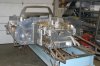
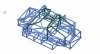
Inspired by the idea of JacMac and with the help of dimensional drawings by Bob Putnam here a completely different frame.
It is not completely original, but made of 6mm aluminium sheet.
Alu honeycomb sandwich is too complicated for me.
Maybe less work than a tube frame, especially if the sheets are laser cut.

It is not completely original, but made of 6mm aluminium sheet.
Alu honeycomb sandwich is too complicated for me.
Maybe less work than a tube frame, especially if the sheets are laser cut.
Should be relatively simple to add all those and more, rear horseshoe was steel bolt in piece with pick-ups for upper links & reverse lower A-Arms, Ive posted pics before of a suitable mounting plate from the forward radsius rods and everything for attaching the front suspension could be bolt on to the tub.
Attachments
Ian Anderson
Lifetime Supporter
Hey Jack - how is your project coming along?
I seem to remember you were doing a MK4
Ian
I seem to remember you were doing a MK4
Ian
Lots of bits & patterns somewhat scattered around the loft upstairs Ian, Life & getting older seems to have got in the road a bit!Hey Jack - how is your project coming along?
I seem to remember you were doing a MK4
Ian
since Corona is also in full control of my business,
I played around with the simulation tool of Fusion360 for fun.
I have simulated the last frame design made of 6mm aluminium plates.
I anchored the front left and rear right panels and loaded the two diagonal panels from below with 12000 N.
The result was a deformation of about 0.6 mm.
Can anyone of you tell me if the simulation setup is correct at all?
And are 12000 N a reasonable size?
Or is this all nonsense I have simulated?
The result looks a bit too good for me
You can find an animation in the attachment.
Attachments
Hi
May I suggest some ...... remarks ?
1/ Torsion on racing cars is not usualy taken in consideration like you did
the front (or the rear) bulkhead is fixed , then aload is apply at various distances on the right and on the left side say 100cm , 150,200 and on the rear bulkhead ( or the front)
2/ In your CAD file does each panel is "CAD welded" ? or the file is an solid extrusion ?
3/ Loads are applied within a lever and gradually to represent afinal effort of 25KN to 40KN depending on what will be the use of that tub
Hope this helps")
May I suggest some ...... remarks ?
1/ Torsion on racing cars is not usualy taken in consideration like you did
the front (or the rear) bulkhead is fixed , then aload is apply at various distances on the right and on the left side say 100cm , 150,200 and on the rear bulkhead ( or the front)
2/ In your CAD file does each panel is "CAD welded" ? or the file is an solid extrusion ?
3/ Loads are applied within a lever and gradually to represent afinal effort of 25KN to 40KN depending on what will be the use of that tub
Hope this helps
Hi
May I suggest some ...... remarks ?
1/ Torsion on racing cars is not usualy taken in consideration like you did
the front (or the rear) bulkhead is fixed , then aload is apply at various distances on the right and on the left side say 100cm , 150,200 and on the rear bulkhead ( or the front)
2/ In your CAD file does each panel is "CAD welded" ? or the file is an solid extrusion ?
3/ Loads are applied within a lever and gradually to represent afinal effort of 25KN to 40KN depending on what will be the use of that tub
Hope this helps
Thank's for your input!
1. That surprises me now, I always thought the torsional stiffness was the most important value !
So if I understand it right, at several points along central axis load should be transferred to both sides?
I have a question about this, if you assume 35KN and e.g. 4 load points, does the total load of 35 KN have to be divided equally, or each point with 35 KN?
2.
All parts of the CAD model are solids
These are connected in the simulation via the "Simulation-Contact" definition
I can also combine all plates to one part in CAD, what would be the difference in the simulation?
3. Could you please explain this a little bit more detailed or make a little sketch, I don't quite understand
Thank's!!
OK;
What I described as a method is one of the variuos method racing team where using some years ago ; may be some one can describe adifferent one
( the chassis done with my method where somewhere good and winners chassis )
1/ the load is applied to those distances only to undertsand how the torsion variesonto the total lenght of the chassis and to understand if there is a"wickness "on the zone where the driver seats due to an sort of "open" side say lower than the front and the rear
this is done onto the right side and then onto the left side just for checking
Yes torsion rate is something importnat but you have also to consider supension rigidity and many other factor so ........................
Evidently the most important torsion rratio to be considered is the one applied at the farest point of the bulhead which is blocked ; it represent
the effort hapenning when hard braking on a very short radius curve
2/ you need to caracterise or each part the material ( what sort of alu ( 7060, 7075 etc etc) or honeycomb or carbon fiber etc etc
3/ you need to apply to each jonction the ratio you have determined ; welding , riveting without bond , riveting and bonded , bonded only etc etc
4/ you need to apply this sort of jonction for alll single parts one to another
All this represent a big hudge work !!! ( I remember doing such simulation on an small helicopter chassis tube ; gave up after 2 months work !!!!)
With modern carbon fiber tubes it was so much more easy and kick , specially because materialmanufacturers where helpfull to give us so many datas
calclated on " scale 1/1 test samples" and the tub was done in 2 or 3 parts bonded and laminated together allowing torsion as it was a solid box !!
What I described as a method is one of the variuos method racing team where using some years ago ; may be some one can describe adifferent one
( the chassis done with my method where somewhere good and winners chassis
)1/ the load is applied to those distances only to undertsand how the torsion variesonto the total lenght of the chassis and to understand if there is a"wickness "on the zone where the driver seats due to an sort of "open" side say lower than the front and the rear
this is done onto the right side and then onto the left side just for checking
Yes torsion rate is something importnat but you have also to consider supension rigidity and many other factor so ........................
Evidently the most important torsion rratio to be considered is the one applied at the farest point of the bulhead which is blocked ; it represent
the effort hapenning when hard braking on a very short radius curve
2/ you need to caracterise or each part the material ( what sort of alu ( 7060, 7075 etc etc) or honeycomb or carbon fiber etc etc
3/ you need to apply to each jonction the ratio you have determined ; welding , riveting without bond , riveting and bonded , bonded only etc etc
4/ you need to apply this sort of jonction for alll single parts one to another
All this represent a big hudge work !!! ( I remember doing such simulation on an small helicopter chassis tube ; gave up after 2 months work !!!!)
With modern carbon fiber tubes it was so much more easy and kick , specially because materialmanufacturers where helpfull to give us so many datas
calclated on " scale 1/1 test samples" and the tub was done in 2 or 3 parts bonded and laminated together allowing torsion as it was a solid box !!
OK I understood that -Thanks for the explanation!
Now I have calculated it again with 35 KN. Result approx. 1.7 mm twist. Safety factor is now down to x1,28
x3 would be better.
What you can see is that the connecting corners need to be reinforced, that's where the highest tensions occur.
All parts are classified as Aluminium 5052
All parts were classified as connected, as I understand this is the closest to welding
I do not have any experience in the field of simulation.
But I think you can gain some knowledge with such simple simulations.
For example, I tried the simulation with the material aluminium 6061, the result of the deformation was nearly the same, but the safety factor increases to 1.8.
If you only look at the stress, you can see that especially the corners are highly loaded.
If you only look at the displacement, it is highest along the X-axis. Here, especially larger radii in the window cut-outs would relieve the firewall wall.
So even as a layman I can derive some practical use from this.
I see all this at the moment only as an indication of where possible weak points are.
Displacement

Stress

Now I have calculated it again with 35 KN. Result approx. 1.7 mm twist. Safety factor is now down to x1,28
x3 would be better.
What you can see is that the connecting corners need to be reinforced, that's where the highest tensions occur.
All parts are classified as Aluminium 5052
All parts were classified as connected, as I understand this is the closest to welding
I do not have any experience in the field of simulation.
But I think you can gain some knowledge with such simple simulations.
For example, I tried the simulation with the material aluminium 6061, the result of the deformation was nearly the same, but the safety factor increases to 1.8.
If you only look at the stress, you can see that especially the corners are highly loaded.
If you only look at the displacement, it is highest along the X-axis. Here, especially larger radii in the window cut-outs would relieve the firewall wall.
So even as a layman I can derive some practical use from this.
I see all this at the moment only as an indication of where possible weak points are.
Displacement
Stress
Now yes you are starting to get much more indications
If you want to be more close to the real deal ; you need now to locate the supension points ( more or less) so you can "block " only from the front
suspensions points ( of course attached to the tub !!) and apply the load with some lever attached to rear supensions ....
Good luck ....
One small remark; 1,7 mm twist is quite a lot ..... you have the risk with this value to get "permanent deformation" specially with welded 6061.....
try to reach only 0.5 to 0.7 mm
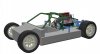
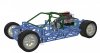
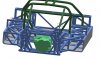
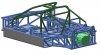
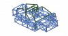
Here's my favorite for the moment.
A tubular frame with the shape of the org. frame.
In the rear however strongly changed, since I do not like the org. suspension in this area so well.
Now I will stop playing with it, my parts have come")
A tubular frame with the shape of the org. frame.
In the rear however strongly changed, since I do not like the org. suspension in this area so well.
Now I will stop playing with it, my parts have come
Attachments
Doc Watson
Lifetime Supporter
Wow... its an engine/gearbox with a bit of ali added.......... would more of a box section in the sills help?
Doc Watson
Lifetime Supporter
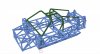
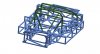
As the external sill shape is nearly a box section, then couldn't you move the 45 degree member to vertical? (red circle) It would also increase the space in there (fuel tank?) and you wouldn't need the extra ribs

Remove the red sections (only highlighted one of the 45 degree sections) and keep, extend and add the yellow sections?

Remove the red sections (only highlighted one of the 45 degree sections) and keep, extend and add the yellow sections?
Similar threads
- Replies
- 2
- Views
- 1K
- Replies
- 0
- Views
- 838