

You are using an out of date browser. It may not display this or other websites correctly.
You should upgrade or use an alternative browser.
You should upgrade or use an alternative browser.
Roaring Forties 105
- Thread starter Jim C
- Start date
Peter Delaney
GT40s Supporter
Absolutely brilliant work Jim !!
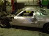
Done a bit more.
Thanks Z ,peter and jimmy.
I ended up putting all the inner panels and heat shield in because I cant play with it once they go in.
It becomes OCD getting small marks or a low spot.
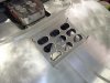
Andy Green you will be pleased to know we have new grills.
One of the Lads that helps me (Rick) put his hand up and he did a great job.
He also made the rear grills, once they went in I had to trim the flanges and reroll them because I could see them through the new grills.
Thanks Z ,peter and jimmy.
I ended up putting all the inner panels and heat shield in because I cant play with it once they go in.
It becomes OCD getting small marks or a low spot.
Andy Green you will be pleased to know we have new grills.
One of the Lads that helps me (Rick) put his hand up and he did a great job.
He also made the rear grills, once they went in I had to trim the flanges and reroll them because I could see them through the new grills.
Attachments
Jim,
Fantastic work as always. If I only had .1% of the metal working skills you posess I would be ecstatic. You do need to keep this car in natural aluminum when you complete it. Even if there are a few bumps and scrapes, it would be a sin to cover this workmanship with paint. And your "streetfighter" approach is perfect. Always a high point for me when you post an update and new photos. Keep of the great work!
Bill
Thanks Bill.
Yes think I will be doing the street fighter thing.
The lumps and bumps give it some history if you know what I mean.
Jim
Yes think I will be doing the street fighter thing.
The lumps and bumps give it some history if you know what I mean.
Jim
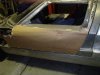
In this post I am revisiting the door I made 8-10 months ago.
I lacked a few skills then and was not happy about a few areas on the door.
1 the front pillar was twice the width.
2 the window was about 20 mm to low, because its not a lot of car I could see it.
I kept thinking it had a chopped look to it, no one else noticed but it bothered me.
3 I used adhesive to glue parts of the door panel because I was worried about panel distortion on welding in the side duct.
4 I glued the pillar panels to the frame because I couldn't get it on in one skin.
The panel I made for the pillar has a step in it, this allows me to run a narrower top outer skin because the outer panel step for the window glass sits into the inner panel step.
This is how I narrowed up the pillar.
I did not remove the whole pillar as I would have to set up the roof height again.
Attachments
Last edited:
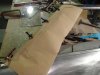
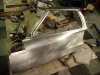
I made a pattern for the door using paper.
I put all the information on the pattern.
I rolled the curve in the top of the door skin in the English wheel.
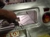
I put the glass recess and mounting flange in one piece.
This was one of the things I didnt do on the last skin and it showed.
Its in pic 5, the red arrows are the recess for the window the panel also has a flange that goes under the window sill and it will be the fixture for the top of the skin to the frame.
Pic 6 is the step dies I machined up to do the form in the sheet for the window.
Cut the door duct and made a section to go in.
Welded and cleaned it up.
You hang it back on to see if it needs adjusting, Adjusting is the technical word for fitting bending and twisting.
I put all the information on the pattern.
I rolled the curve in the top of the door skin in the English wheel.
I put the glass recess and mounting flange in one piece.
This was one of the things I didnt do on the last skin and it showed.
Its in pic 5, the red arrows are the recess for the window the panel also has a flange that goes under the window sill and it will be the fixture for the top of the skin to the frame.
Pic 6 is the step dies I machined up to do the form in the sheet for the window.
Cut the door duct and made a section to go in.
Welded and cleaned it up.
You hang it back on to see if it needs adjusting, Adjusting is the technical word for fitting bending and twisting.
Attachments
Last edited:
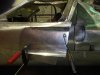
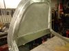
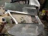
The2nd pic is the roof section in the door.
The box area out towards the window I had an issue with.
It was a bit close when you have a helmet on and I wasn't happy with the general shape.
To be honest I think I just ran out off ideas when I was making it.
Because of the pillar mod I decided to fix this as well.
My best option was to cut back and reweld in a panel rather than grind and clean the welds off.
I put a return out at the windows upper edge of this panel for the roof skin to mount to.
Attachments
Last edited:
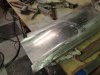
The roof skin I obviously had to remake.
remade it with the window recess rolled into the skin.
All the window flanges I tried to keep at about the 12-13mm.
The next step was the pillar covers.
Another pattern, using Peters method of transferring the info across.
I beaded in the step and used a combo of roller and ewheel to achieve the curve in the panel after the step was done.
Attachments
Last edited:
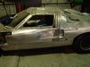
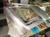
I never attached the pillar skins to the roof or door on the last attempt because I didn't feel I would get the complete item on in one hit.
I wanted to try it on this one so I set it up and welded them to the roof and door skin.
It was snug coming off so I did a little trimming here and there on excess material to ease its assembly.
Did a clean on the inside so it would sit down on the frame.
I had to clean the lower rear rad in the recess as it changed a little as it exited the bead roller die , I did a little tidy up by hand afterward.
A few pics of the skin off and on.
I am generally happy with the result.
Attachments
Last edited:
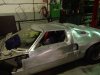
Did an assemble with a sealer.
Had to cut a section in top front pillar to get the assembly on.
I would rather put larger patches than little ones, its easier.
I have to trim in the rear of the duct and a little setting of hieghts on the panels but its there.
I have to sort the centre pillar alignment at the top of the duct but I will do that when the other door is made.
Will start on the R/H door next week
That's it Jim
Attachments
Last edited:
hello jim great work as usual
and that rick is a clever buggar as well
he did a terrific job on those vents
jim how many hours a week do you put
in to the gt?
chris
Rick did a great job on the vents.
He did the deck vent 3 times due to silly errors.
Hes good at it know, if you need advice ask Rick, practice practice practice.
2nd part of your question.
I spend all day Saturday, a 12hr day.
I try to put in a 1-3 hours in the morning before work.
I do this so I can get an extra 1/2 to full day in.
If I go to bed thinking about it I will be up at 4am and gone.
My home is only about 10 min from my factory so I dont waist time in the car.
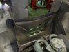
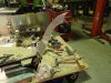
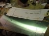
This post I took more photos of the drivers door being made from scratch.
Its not complete yet but I will post the rest up in a week or so.
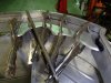
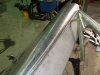
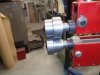
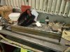
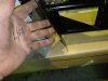
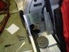
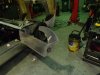
First thing I have to do is make the intrusion bar.
I made the hinge pin tube first then a rear plate for the lock assembly to mount to.
I attach the lock and fit it onto the striker.
I then fit up one tube and tack it in, once happy I do the second tube.
Once I am happy with the fit and open close I put some gussets in, weld the tubes and gussets.
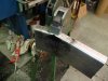
2 strips of 1mm sheet is used to cover in the tubes.
I use the bead roller to put the ribs in the sheet, this adds a huge amount of strength.
Weld the sheets to the tubes.
In The sheet work I drill 2 holes and same in the end of the tube, I then inject the frame with 3m pillar foam, It is a 2 pac closed cell foam designed for impact area.
This adds more strength but allows me to keep the weight down.
I should have taken more pics as I was building this but you get involved.
The whole build of the bar was 3-4 hrs including paint.
Attachments
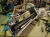
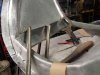
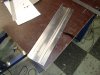
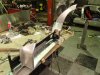
Once the bar is made I then move onto the alloy work.
I have the L/H door finished so I use it a s a guide as you are trying to make them look the same.
The floor is the first piece, the pattern is marked out to suit the floor shape and into the dash.
I drop a rule down of the lock mount of the intrusion bar to give me the rear of the door on the pattern.
The pattern fold over the side of the sill will be the flange for the door skin to mount to.
I cut the sheet to suit the pattern and fold the flange for the skin to mount to.
The flange is larger than required but it will be trimmed later to suit any adjustments.
I use a T dolly and a wooden slapper that I made.
You just tap it over the dolly and this gives me the radius that I am chasing around the frame edges.
It is much easier to file finish and it softens the look( more like the glass doors) rather than being a square box.
Attachments
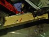
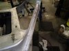
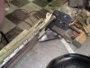
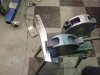
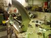
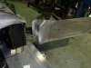
Next panel is the lower rear, pattern it out cut and roll the lower edge.
I marked out the holes for the lock assembly and sandwich it between the lock and intr/bar.
The next panel is a support for the door, it is just a sheet with a fold and a bead.
The bead is so it sits flat on the side of the int/bar and clears the bead on the bar.
This gets riveted to the bar and floor.
A fold is put on the back panel.
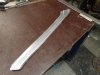
A pattern is made of the rear pillar outer skin.
I use the bead roller to fold the edge up as its going around a corner you cant use a folder.
As it comes over I have to shrink the flange as it is longer and as you bend it will curve the sheet so I try to control it to a point.
Once folded I have to straighten it out to suit the pillar and I do this in the shrinker.
I marked out the holes for the lock assembly and sandwich it between the lock and intr/bar.
The next panel is a support for the door, it is just a sheet with a fold and a bead.
The bead is so it sits flat on the side of the int/bar and clears the bead on the bar.
This gets riveted to the bar and floor.
A fold is put on the back panel.
A pattern is made of the rear pillar outer skin.
I use the bead roller to fold the edge up as its going around a corner you cant use a folder.
As it comes over I have to shrink the flange as it is longer and as you bend it will curve the sheet so I try to control it to a point.
Once folded I have to straighten it out to suit the pillar and I do this in the shrinker.
Attachments
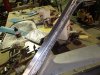
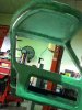
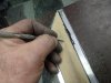
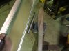
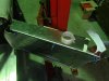
A rolled edge is put on the inside edge.
The welded into position.
The front panel is made to suit.
I anneal the sheet then stretch the flange to get it to curve, the curve has to suit the dash .
This is tacked in.
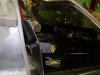
When all the panels go on the door has to go on and checked for fit.
You pull it off and weld then refit and check.
The welded into position.
The front panel is made to suit.
I anneal the sheet then stretch the flange to get it to curve, the curve has to suit the dash .
This is tacked in.
When all the panels go on the door has to go on and checked for fit.
You pull it off and weld then refit and check.
Attachments
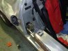
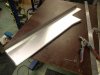
When the front rear panels are in then you fill in the space in between.
I cut a general size and mark out the step for the door pocket.
When I step the panel it changes the outer dimension of the panel slightly.
So step first then mark out and cut as per pattern.
You fettle away to get it to fit nice
I weld it in then run around a do a file up on the welds.
The top panel is folded as it travels over the top corner by 30mm.
That is where the weld will be.
Attachments
Last edited:
Similar threads
- Replies
- 139
- Views
- 18K