
- Forums
- GT40 Replica Manufacturers' Corner
- RCR Forum - RCR40/SLC/917/Superlite Aero
- The SLC Clubhouse
You are using an out of date browser. It may not display this or other websites correctly.
You should upgrade or use an alternative browser.
You should upgrade or use an alternative browser.
S2's Build Thread
- Thread starter sswartz
- Start date
Scott
Lifetime Supporter
Joel,
I haven't found any documentation on the iBooster, so I'm going to have to try it and see what happens. A couple of thoughts:
I don't think that the amount of boost for vacuum-assisted brakes will be completely consistent because the amount of boost is dependent on the pressure differential between the two sides of the diaphragm, neither of which is constant. The difference on the atmospheric side will vary by 26% between sea level and 8,000 feet and I assume that vacuum will vary depending on what the engine is doing. Probably not enough to notice, but I think any calculation will make assumptions.
The iBooster ratio is set by #2 Boost Ratio show below. It appears to be linear with the slope of the line being configurable. That said, I haven't figured out how to control that via CAN bus, so there must be a default value for the fail-safe mode. I don't know if different OEMs flash different default values to the ECU or if it's consistent. You will also note that both the Jump In and Run Out pressure points are configurable.

I would not want to move the linkage up on the Tilton brake pedal. It's cast aluminum and appears to have been carefully designed with finite-element analysis (FEA) to remove every gram of weight. The area above the stock balance bar location is heavily scalloped and would not be sufficiently strong. Power brakes will reduce brake pedal force, but if the brake booster fails the mechanism must still support a two-foot emergency stop. I'm finishing up an adapter to replace the balance bar and I'm focused on the brake pedal being able to exercise the iBooster's full stroke. I designed everything as compact as possible, I might need to stretch the bracket.
Hopefully I can get to where I need to be with that approach. I'm fairly confident that if someone figures out how to hack the CAN bus (or gets their hands on some Bosch documentation) I would be able to configure exactly what I want. If I can't configure the CAN bus and I can't find a master cylinder that gets me what I want with the fail-safe mode, then I'm stuck with a bellcrank. As I pointed out in the initial post, I'd rather not go that route.
I haven't found any documentation on the iBooster, so I'm going to have to try it and see what happens. A couple of thoughts:
I don't think that the amount of boost for vacuum-assisted brakes will be completely consistent because the amount of boost is dependent on the pressure differential between the two sides of the diaphragm, neither of which is constant. The difference on the atmospheric side will vary by 26% between sea level and 8,000 feet and I assume that vacuum will vary depending on what the engine is doing. Probably not enough to notice, but I think any calculation will make assumptions.
The iBooster ratio is set by #2 Boost Ratio show below. It appears to be linear with the slope of the line being configurable. That said, I haven't figured out how to control that via CAN bus, so there must be a default value for the fail-safe mode. I don't know if different OEMs flash different default values to the ECU or if it's consistent. You will also note that both the Jump In and Run Out pressure points are configurable.
I would not want to move the linkage up on the Tilton brake pedal. It's cast aluminum and appears to have been carefully designed with finite-element analysis (FEA) to remove every gram of weight. The area above the stock balance bar location is heavily scalloped and would not be sufficiently strong. Power brakes will reduce brake pedal force, but if the brake booster fails the mechanism must still support a two-foot emergency stop. I'm finishing up an adapter to replace the balance bar and I'm focused on the brake pedal being able to exercise the iBooster's full stroke. I designed everything as compact as possible, I might need to stretch the bracket.
Hopefully I can get to where I need to be with that approach. I'm fairly confident that if someone figures out how to hack the CAN bus (or gets their hands on some Bosch documentation) I would be able to configure exactly what I want. If I can't configure the CAN bus and I can't find a master cylinder that gets me what I want with the fail-safe mode, then I'm stuck with a bellcrank. As I pointed out in the initial post, I'd rather not go that route.
Scott
Lifetime Supporter
I'm not sure. People seem to be happy with the results, but I haven't seen anyone measure things. I have a digital 600-pound hanging scale and I'm thinking about setting up a bench test rig with a come-along to pull the brake pedal from the back. I would then connect a pressure gauge to both the front and rear pressure outlets. This would enable me to determine the front/rear bias a well as the hydraulic pressure with the iBooster powered and unpowered. It would also be interesting to see if I could determine the Jump-In and Runout Pressure points. That said, it would save a lot of time if someone could get their hands on some documentation or find the right contact at Bosch to ask a couple of basic questions.Based on other users, how aggressive is the assist in stand-alone mode?
Note that while there is only one input rod, I believe that there are two master cylinders. That seems logical and when I removed the reservoir there were two feeds. Part of the reason that I'm comfortable with this approach is that Bosch is a world-class company with a lot of experience with brakes/ABS and the units are on a lot of OEM cars. Here's an excerpt from their marketing material.In case of failure, I'm assuming that the master cylinder will function in the same manner as a typical booster failure?
The iBooster has a two-phase safety concept... In the second safety phase, the mechanical push-through mechanism is available as a backup if the on-board power supply fails: the driver can apply the wheel brakes on all four wheels via a hydraulic mode without the brake booster effect, thereby safely bringing the vehicle to a stop and satisfying statutory requirements in full.
Frank Clark
Supporter
Like I said an interesting tuning problem. Active ride height anyone?
Bump springs can help a lot.... just one more tuning aid. I have two stages (three springs total) that engage as the car gets lower (or wheel gets higher).
Scott
Lifetime Supporter
Frank, I did a lot of research when getting my Penske shocks to fit properly. I spoke with someone who gets paid a lot of money to tune progressive spring rates like the ones shown below. For my purposes, I have a main spring, a bump spring and a bump stop. Once I get the car on the track, I'll figure out if I need to do something more complex.

Scott
Lifetime Supporter
In a previous post, I discussed my plan to implement power brakes with a GEN1 Bosch iBooster, I fabricated a bracket to mount it and I machined the pedal box.
The next step was to connect the brake pedal to the iBooster. Since the iBooster has only one input rod the front/rear brake bias will be adjusted via a hydraulic proportioning valve rather than the balance bar that came with the pedal box. I removed the balance bar and was surprised at how small the mechanism was. I would have thought that more contact area would be required, especially given that the pedals are cast aluminum, but the Tilton guys know what they’re doing.

Stock balance bar (left) and custom balance bar replacement (right). Note that the bolt heads are drilled for a safety wire.
I wanted to replace the balance bar with something that was unquestionably strong and had a precision fit. I’m pretty sure that 6061 aluminum would have been strong enough, but when dealing with brakes it makes sense to be conservative. I considered using steel, but it’s heavy and it would rust inside the pedal. McMaster offers tight-tolerance (0.0005" to 0.0000") high-strength 7075 aluminum rod. While it doesn’t like to be bent, it’s incredibly strong which is why it’s used in aerospace for structural applications.

Using the lathe, I machined the rod a few thousands wider than the pedal and drilled and tapped 5/16"-24 holes in the ends. While there should be minimal lateral forces, I laser cut retention discs from 0.060" stainless steel to restrict lateral movement. The 5/16"-24 rod ends are held in place by grade 8 washers and hex bolts with drilled heads so that they can be safety wired.
I removed the clevis from the iBooster’s input rod to keep everything compact and to reduce the number of connections that might introduce play into the braking motion. Note that some OEMs utilize an extension rather than a clevis. I then fabricated an adapter from 1/2” x 3/4” 4140 bar, 1/2” OD 0.058” wall 4130 tube and 5/16”-24 4130 tube ends. The center was tapped for the input shaft’s M10 x 1.5 mm thread and I bored holes 80% of the way into bar to receive the tubes. It would have been less work to fillet weld the tubes to the bar, but the bored holes help jig the tubes during welding and they result in a stronger assembly.

Parts ready for welding; adapter bar (left), tubes (middle) and tube ends (right)

The adapter connects the two rod ends bolted to the brake pedal insert to the iBooster’s input rod. The tube ends haven’t been tacked yet and the input rod’s bellow has been temporarily removed.
While the base of the tubes were jigged, I didn’t jig the ends of tubes and one of them warped inwards during welding, so I’ll need to remake this part. I’m worried about having enough master cylinder travel so the iBooster is spaced 1/4” off of the bracket, the tubes were left long and the tube ends are only lightly tacked. Without any fluid in the system, I pressed the brake pedal until it bound on the adapter bar. This resulted in about 5-1/4” pedal travel, as measured from the middle of the pedal, and about 15/16” of master cylinder travel. From what I can tell, the master cylinder has a 1” bore which would mean that I shouldn’t need much travel. However, I think that the single input rod drives two internal master cylinders (the reservoir has two feeds) and I have no idea how that changes things.
The master cylinder has two M12 x 1.0 mm pressure ports, so I purchased a set. D’oh! The seat is deeply recessed and the hex nut bottomed before the flare seated. No one seems to spec how far the threads extend which required looking at a lot of pictures to find one that would work. Fortunately, the second time was the charm and K-Motor Performance had the solution.

M12 x 1.0 mm to -3 AN fittings; note how much longer the M12 threads (the ones pointing down) are on the right fitting offered by K-Motor Performance
There are lot of unknowns regarding master cylinder travel, how the internal master cylinders are sized, the size of caliper pistons (although I could figure that one out). So, the next step is to plumb the iBooster into the car and see what happens. I’ll measure the pressure at the front and rear calipers with a gauge both with and without the iBooster powered up. That should give me a good idea if I have enough pedal travel, what the amount of boost is and if the master cylinder size provides enough volume for my brakes. I have the Brembo GT upgrade, so I’ll need more volume than the stock brakes.
The next step was to connect the brake pedal to the iBooster. Since the iBooster has only one input rod the front/rear brake bias will be adjusted via a hydraulic proportioning valve rather than the balance bar that came with the pedal box. I removed the balance bar and was surprised at how small the mechanism was. I would have thought that more contact area would be required, especially given that the pedals are cast aluminum, but the Tilton guys know what they’re doing.
Stock balance bar (left) and custom balance bar replacement (right). Note that the bolt heads are drilled for a safety wire.
I wanted to replace the balance bar with something that was unquestionably strong and had a precision fit. I’m pretty sure that 6061 aluminum would have been strong enough, but when dealing with brakes it makes sense to be conservative. I considered using steel, but it’s heavy and it would rust inside the pedal. McMaster offers tight-tolerance (0.0005" to 0.0000") high-strength 7075 aluminum rod. While it doesn’t like to be bent, it’s incredibly strong which is why it’s used in aerospace for structural applications.
Using the lathe, I machined the rod a few thousands wider than the pedal and drilled and tapped 5/16"-24 holes in the ends. While there should be minimal lateral forces, I laser cut retention discs from 0.060" stainless steel to restrict lateral movement. The 5/16"-24 rod ends are held in place by grade 8 washers and hex bolts with drilled heads so that they can be safety wired.
I removed the clevis from the iBooster’s input rod to keep everything compact and to reduce the number of connections that might introduce play into the braking motion. Note that some OEMs utilize an extension rather than a clevis. I then fabricated an adapter from 1/2” x 3/4” 4140 bar, 1/2” OD 0.058” wall 4130 tube and 5/16”-24 4130 tube ends. The center was tapped for the input shaft’s M10 x 1.5 mm thread and I bored holes 80% of the way into bar to receive the tubes. It would have been less work to fillet weld the tubes to the bar, but the bored holes help jig the tubes during welding and they result in a stronger assembly.
Parts ready for welding; adapter bar (left), tubes (middle) and tube ends (right)
The adapter connects the two rod ends bolted to the brake pedal insert to the iBooster’s input rod. The tube ends haven’t been tacked yet and the input rod’s bellow has been temporarily removed.
While the base of the tubes were jigged, I didn’t jig the ends of tubes and one of them warped inwards during welding, so I’ll need to remake this part. I’m worried about having enough master cylinder travel so the iBooster is spaced 1/4” off of the bracket, the tubes were left long and the tube ends are only lightly tacked. Without any fluid in the system, I pressed the brake pedal until it bound on the adapter bar. This resulted in about 5-1/4” pedal travel, as measured from the middle of the pedal, and about 15/16” of master cylinder travel. From what I can tell, the master cylinder has a 1” bore which would mean that I shouldn’t need much travel. However, I think that the single input rod drives two internal master cylinders (the reservoir has two feeds) and I have no idea how that changes things.
The master cylinder has two M12 x 1.0 mm pressure ports, so I purchased a set. D’oh! The seat is deeply recessed and the hex nut bottomed before the flare seated. No one seems to spec how far the threads extend which required looking at a lot of pictures to find one that would work. Fortunately, the second time was the charm and K-Motor Performance had the solution.
M12 x 1.0 mm to -3 AN fittings; note how much longer the M12 threads (the ones pointing down) are on the right fitting offered by K-Motor Performance
There are lot of unknowns regarding master cylinder travel, how the internal master cylinders are sized, the size of caliper pistons (although I could figure that one out). So, the next step is to plumb the iBooster into the car and see what happens. I’ll measure the pressure at the front and rear calipers with a gauge both with and without the iBooster powered up. That should give me a good idea if I have enough pedal travel, what the amount of boost is and if the master cylinder size provides enough volume for my brakes. I have the Brembo GT upgrade, so I’ll need more volume than the stock brakes.
Attachments
I'm on the edge of my seat as you get closer to testing out this iBooster setup. I'm loving your detailed write ups around many of the small engineering decisions you are making to adapt this booster to the Tilton pedals.
1. How much farther does the iBooster stickout than a normal Tilton + Master cylinder setup?
2. I will now have to refer to washers as "retention discs", sounds way better")
1. How much farther does the iBooster stickout than a normal Tilton + Master cylinder setup?
2. I will now have to refer to washers as "retention discs", sounds way better
Scott
Lifetime Supporter
Mason,
Everything is plumbed in the car for a test, so I can't easily measure it now. The unit sticks out a lot further than the standard master cylinder. However, Allan installed my pedals where he does for everyone regardless of height (apparently he typically makes up the difference with the seat location and tilt). My guess is that a really tall person might want the pedals moved forward a bit, but to my recollection there were at least a couple of additional inches before the unit would hit the vertical face of the extended footbox. I'll measure it when I have it out of the car.
=======
I’ve used SendCutSend to laser cut many aluminum, 4130 and titanium parts, but I had never used their bending services. Last week I needed to fabricate a bunch of brackets with precise bends, so I decided to give their service a whirl. I was specifically curious how close the actual parts would be to the 3D-printed prototypes.

The bent brackets (green) will support the heatshield (mauve) and attach to the transaxle via the vibration/heat isolators (purple). The rear bracket will also provide support for the X-pipe. There will be at least 6 and potentially as many as 8 different brackets.
I didn’t use SendCutSend’s online bend calculator because I had already designed the brackets using Solidwork’s sheet metal features which automatically takes into account bend allowances. I highly recommend that you use a CAD-based sheet metal tool to design these types of parts because; (1) it makes things infinitely easier to design the part, (2) you can 3D print prototypes and (3) you can create assemblies like the one pictured above to tweak and validate the design.
SendCutSend’s bending guidelines are helpful and easy to understand. The only thing that I needed to change in Solidworks was to set the K Factor and Bend Radius values to what was spec’d on SendCutSend’s website for the material being bent. This changed the bend profile a bit, so I reprinted the prototype brackets. I then exported the flat patterns to DXF files ensuring that the bend lines were included, uploaded the files to SendCutSend and indicated if the bend lines should be oriented up or down. Wow, that was easy.

SendCutSend laser cut and bent these parts from 1/8” 5052 aluminum. While these brackets only have a simple 90-degree bend, SendCutSend supports significantly more complex bends.

Left/right mirrored versions of the same bracket to compare the 3-D printed prototype to the final bent aluminum part. The match is pretty much perfect as far as I can tell.
In low volume, each bend costs $2 with a $9 bend minimum. For example, one bend will cost you $9, but 5 bends will only cost $10 (I think I got that right, but their quoting is transparent and instantly updates). The good news, is that the minimum applies to the whole order and not a specific part. This is an excellent deal if you think about it. In my neck of the woods a fabricator costs $120/hour which equates to $2/minute. It would take an expert with a non-CNC brake longer than that to mark the part, align it and bend it. I could have easily bent these parts in my brake for free, but it would have been impossible to be as precise. In addition, while my brake has fingers, they all have the same profile which is fairly pointed. SendCutSend has specific dies for every thickness of material that they bend which, as proven above, means that I can almost perfectly model bent parts (as least simple ones).
The only downside is that bending will add a couple of days to the typical one-week delivery time. I have some more complicated parts that require bending and it looks like SendCutSend will handle any of the parts that I will draw in CAD.
Everything is plumbed in the car for a test, so I can't easily measure it now. The unit sticks out a lot further than the standard master cylinder. However, Allan installed my pedals where he does for everyone regardless of height (apparently he typically makes up the difference with the seat location and tilt). My guess is that a really tall person might want the pedals moved forward a bit, but to my recollection there were at least a couple of additional inches before the unit would hit the vertical face of the extended footbox. I'll measure it when I have it out of the car.
=======
I’ve used SendCutSend to laser cut many aluminum, 4130 and titanium parts, but I had never used their bending services. Last week I needed to fabricate a bunch of brackets with precise bends, so I decided to give their service a whirl. I was specifically curious how close the actual parts would be to the 3D-printed prototypes.
The bent brackets (green) will support the heatshield (mauve) and attach to the transaxle via the vibration/heat isolators (purple). The rear bracket will also provide support for the X-pipe. There will be at least 6 and potentially as many as 8 different brackets.
I didn’t use SendCutSend’s online bend calculator because I had already designed the brackets using Solidwork’s sheet metal features which automatically takes into account bend allowances. I highly recommend that you use a CAD-based sheet metal tool to design these types of parts because; (1) it makes things infinitely easier to design the part, (2) you can 3D print prototypes and (3) you can create assemblies like the one pictured above to tweak and validate the design.
SendCutSend’s bending guidelines are helpful and easy to understand. The only thing that I needed to change in Solidworks was to set the K Factor and Bend Radius values to what was spec’d on SendCutSend’s website for the material being bent. This changed the bend profile a bit, so I reprinted the prototype brackets. I then exported the flat patterns to DXF files ensuring that the bend lines were included, uploaded the files to SendCutSend and indicated if the bend lines should be oriented up or down. Wow, that was easy.
SendCutSend laser cut and bent these parts from 1/8” 5052 aluminum. While these brackets only have a simple 90-degree bend, SendCutSend supports significantly more complex bends.
Left/right mirrored versions of the same bracket to compare the 3-D printed prototype to the final bent aluminum part. The match is pretty much perfect as far as I can tell.
In low volume, each bend costs $2 with a $9 bend minimum. For example, one bend will cost you $9, but 5 bends will only cost $10 (I think I got that right, but their quoting is transparent and instantly updates). The good news, is that the minimum applies to the whole order and not a specific part. This is an excellent deal if you think about it. In my neck of the woods a fabricator costs $120/hour which equates to $2/minute. It would take an expert with a non-CNC brake longer than that to mark the part, align it and bend it. I could have easily bent these parts in my brake for free, but it would have been impossible to be as precise. In addition, while my brake has fingers, they all have the same profile which is fairly pointed. SendCutSend has specific dies for every thickness of material that they bend which, as proven above, means that I can almost perfectly model bent parts (as least simple ones).
The only downside is that bending will add a couple of days to the typical one-week delivery time. I have some more complicated parts that require bending and it looks like SendCutSend will handle any of the parts that I will draw in CAD.
Scott
Lifetime Supporter
I’ve removed/installed the cage many times and it’s a pretty quick and easy process. However, it’s a royal pain in the ass to install the rod ends that connect the rear legs to the top of the rear hoop. It takes me longer to install those two bolts, than it does to install the other 14 bolts combined. The issue is that the standard RCR suspension bracket is utilized which requires a high-misalignment rod end, two aluminum misalignment washers and a grade-8 washer to be crammed at an awkward angle. In fact, the body of one of my rod ends actually binds on the bracket. It’s difficult to get the washers and misalignment washers in place, let alone properly aligned, and if they fall you need to find them all because one might be in the supercharger, accessory or dry sump belt. Sometimes one hits the floor and rolls to God knows where and you can spend a lot of time looking for it on the floor or on the front engine dress. Last thing you want is foreign-object damage when you start the engine.
Conceptually this isn’t problem because the rear legs aren’t removed very often once the car is finished and you want everything tight.
HOWEVER, as can be seen in the picture below, the body significantly overhands the rod ends and it’s somewhere between a nightmare and impossible to install things when the body is on. I struggle to install the rod ends and washers when the body is removed, I’m standing in the center of the cockpit and have prefect access to everything. With the body on, it would be easy to get the rod end installed, but the misalignment washers and grade 8 washer — NFW.

The carboard simulates the body. Note how far it overhangs the rod end
Given that I must remove the rear hoop legs to remove the engine and removing the body requires removing the doors, headliner, windshield (which I risk cracking) and removing and then reinstalling all of the sealing around the foot box, side pods and firewall, this is an untenable situation.
I considered welding a section of tube to a plate mounted to the firewall and using interlocking tube couplers to enable a section of the leg to be easily removed. The issue with that approach is that the tubes welded to the firewall would need to extend an inch or so past the body which, as shown above, extends well into the engine compartment and, at least in my case, would cause them to interfere with the supercharger during engine removal.
I settled on a three-part solution:

Rear hoop leg being sectioned with a horizontal bandsaw… no going back now!
 \
\
I used high-quality 4130 tube ends. They project ~2.5x further into the tube than the stock pieces which provides more thread engagement and improved resistance to lateral loads. Abe showed me a fabrication technique that he learned during his days building high-HP drag chassis. He would bore four holes in the tube 90 degrees apart to add rosette welds in addition to the standard circumference/edge weld. While this increases the amount of weld contact, the primary purpose is to reduce lateral stresses on the edge weld by anchoring the inserted portion of the tube end to the tube. A center-cutting end mill works much better than a drill bit when creating a hole on a radius.
The bracket was a bit tricky to fabricate. Given the material thicknesses and size of the parts, I only designed a single slot and tab. The challenge was that the clevis plate is angled at 60 degrees which required the edge that mates with the base plate and the matching slot in the base plate to be beveled at 60 degrees. To accomplish this, I purchased an inexpensive (about $85) tilting vice. It’s not intended for milling, but I took very light cuts and it worked well. To reduce the size of the bracket the outside gusset was angled which required some grinding of the clevis and base plates.


The clevis plate is 3/8” (that’s what the slot clevis requires), the base plate is 1/4” (I didn’t want it to warp while welding the thick clevis plate), and the gussets are 0.190”, all of which were laser cut. The slot isn’t pretty because I wasn’t going for style points when filing the corners and the fit up was good for welding purposes.

The edge of the angled clevis plate being milled at 60 degrees (the 30 degrees indicated on the vice is the reverse angle)

The upper and lower edges of the laser-cut slot in base plate about to be milled at 60 degrees (the 30 degrees indicated on the vice is the reverse angle). The end mill left rounded corners which were manually filed square.
To ensure that everything was aligned the tube ends were welded, the link was installed, the base plate was mounted to the firewall, the clevis plate was bolted to the clevis and a small amount of compression preload we applied (i.e., the link pushing the clevis plate into the base plate). A couple of clamps were added and the bracket was heavily tacked. After the bracket cooled, welding was completed on the bench.

Stock leg (left) and modified leg (right). 3/4”-16 RHT slot clevis at the top and matching LHT tube ends and floating grade 8 threaded rod at the bottom.
Wow it’s easy to install/deinstall the rear hoop legs. Nothing dropped, no profanity and to top it off I can set the perfect amount of preload. I’m very happy with this modification.
The next step is to finish the left side.
Conceptually this isn’t problem because the rear legs aren’t removed very often once the car is finished and you want everything tight.
HOWEVER, as can be seen in the picture below, the body significantly overhands the rod ends and it’s somewhere between a nightmare and impossible to install things when the body is on. I struggle to install the rod ends and washers when the body is removed, I’m standing in the center of the cockpit and have prefect access to everything. With the body on, it would be easy to get the rod end installed, but the misalignment washers and grade 8 washer — NFW.
The carboard simulates the body. Note how far it overhangs the rod end
Given that I must remove the rear hoop legs to remove the engine and removing the body requires removing the doors, headliner, windshield (which I risk cracking) and removing and then reinstalling all of the sealing around the foot box, side pods and firewall, this is an untenable situation.
I considered welding a section of tube to a plate mounted to the firewall and using interlocking tube couplers to enable a section of the leg to be easily removed. The issue with that approach is that the tubes welded to the firewall would need to extend an inch or so past the body which, as shown above, extends well into the engine compartment and, at least in my case, would cause them to interfere with the supercharger during engine removal.
I settled on a three-part solution:
- Replace the 90-degree bracket with a custom bracket that matches the downward angle of the rear leg. This solves the root of the problem.
- Replace the 1/2” right-hand-thread (RHT) high-misalignment rod end, misalignment washers and grade-8 washer with a 3/4” RHT slot clevis. This is more robust, has three less parts to drop and there is zero struggle to line things up.
- Make the leg indexable by sectioning it and welding two 3/4” left-hand-thread (LHT) tube ends and a floating 3/4” grade-8 threaded rod. This makes it even easier to install/remove the leg and enables me to apply the perfect amount of preload.
Rear hoop leg being sectioned with a horizontal bandsaw… no going back now!
I used high-quality 4130 tube ends. They project ~2.5x further into the tube than the stock pieces which provides more thread engagement and improved resistance to lateral loads. Abe showed me a fabrication technique that he learned during his days building high-HP drag chassis. He would bore four holes in the tube 90 degrees apart to add rosette welds in addition to the standard circumference/edge weld. While this increases the amount of weld contact, the primary purpose is to reduce lateral stresses on the edge weld by anchoring the inserted portion of the tube end to the tube. A center-cutting end mill works much better than a drill bit when creating a hole on a radius.
The bracket was a bit tricky to fabricate. Given the material thicknesses and size of the parts, I only designed a single slot and tab. The challenge was that the clevis plate is angled at 60 degrees which required the edge that mates with the base plate and the matching slot in the base plate to be beveled at 60 degrees. To accomplish this, I purchased an inexpensive (about $85) tilting vice. It’s not intended for milling, but I took very light cuts and it worked well. To reduce the size of the bracket the outside gusset was angled which required some grinding of the clevis and base plates.
The clevis plate is 3/8” (that’s what the slot clevis requires), the base plate is 1/4” (I didn’t want it to warp while welding the thick clevis plate), and the gussets are 0.190”, all of which were laser cut. The slot isn’t pretty because I wasn’t going for style points when filing the corners and the fit up was good for welding purposes.
The edge of the angled clevis plate being milled at 60 degrees (the 30 degrees indicated on the vice is the reverse angle)
The upper and lower edges of the laser-cut slot in base plate about to be milled at 60 degrees (the 30 degrees indicated on the vice is the reverse angle). The end mill left rounded corners which were manually filed square.
To ensure that everything was aligned the tube ends were welded, the link was installed, the base plate was mounted to the firewall, the clevis plate was bolted to the clevis and a small amount of compression preload we applied (i.e., the link pushing the clevis plate into the base plate). A couple of clamps were added and the bracket was heavily tacked. After the bracket cooled, welding was completed on the bench.
Stock leg (left) and modified leg (right). 3/4”-16 RHT slot clevis at the top and matching LHT tube ends and floating grade 8 threaded rod at the bottom.
Wow it’s easy to install/deinstall the rear hoop legs. Nothing dropped, no profanity and to top it off I can set the perfect amount of preload. I’m very happy with this modification.
The next step is to finish the left side.
Howard Jones
Supporter
When I take my chassis braces off to remove the engine I remove the big bolt on the bottom "Y" section and then unscrew the tube from the rod end leaving it in place on the through bolt at the top. Really very simple to do. However, I really like your solution. Well done.
Scott
Lifetime Supporter
Howard,
Good suggestions. I have used the method that you described above to install/deinstall the rear legs, but it doesn't work for me with the engine in because the Y-section collides with my headers. They're an equal-length, 180-degree cross under design and, like many exotics, they must be removed with the engine. Beyond the install/deinstall hastle, I don't like the stock approach for the following reasons:
(1) The car has a 6-point cage and 2 of those points go through 1/2" rod ends. To put that in perspective, that's the same architecture that's used for a single control arm. Since a front upright has two control arms it has twice the attachment points as one third of the cage attachment points (i.e., the two at the top of the hoop). I fully understand that components are ideally designed to dissipate energy via mechanical fuses, deformation, etc. in a crash, but that upright to cage ratio doesn't seem right to me. Keep in mind the rod ends on the control arms are perfectly straight whereas the ones in the cage are at an acute angle. In addition, the provided cone washers are aluminum which is great for a control arm, but not correct for a cage.
I'm not aware of a SL-C that's flipped over - let's hope one never does. It seems pretty unlikely to happen on the street unless you're doing something stupid. However, the SL-C is very low. In a rearend collision a truck with a little lift could easily ride up over the engine and onto the rear hoop legs. The junction that I'm talking about is literally inches from the driver's and passenger's heads. I personally want that junction to be as strong as possible. As described in my initial post, the best solution would be a solid plate with welded and gusseted tubes with interlocking connectors. That won't work for me, so my solution is a compromise in terms of strength, but it's certainly more robust than stock.
(2) I like having the correct amount of preload. The easiest way to achieve that is with an indexable link.
Last edited:
Joel K
Supporter
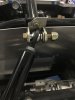
As usual Scott. Really nice work. Sort of curious. The brackets and/or rod ends provided in my kit must be different than what you have. I don’t have misalignment spacers for the rear cage bars. Just have one flat washer. Attached is a pic…
Attachments
Scott
Lifetime Supporter
Joel,
Mine was different. In my experience the critical stuff like the welds, machining, general architecture, etc. are top notch, but the assembly to ship the car is extremely variable and depends on who did it and how rushed they were to push it out the door. For example, I had issues with my Penske shocks and when I spoke to the person at RCR who installed them he told me that it took two people and a crowbar. Ahh… that’s not right, it explains the scratches on the cherry parts and why I can’t get them back in. He’s the same person that installed my rear hoop legs, so I’m not surprised that my set up was different than yours.
The manual does point out that the car was assembled for shipping purposes and that the builder is responsible. The issue is that I never got a parts list and there is little to no documentation. I assume that every nut, bolt, washer and part is suspect until I know otherwise.
Looking at your picture… I think that you want to point the bolt the other way. I’m pretty sure that in the current orientation, that the bolt can’t be removed with the body on.
I finished the left side yesterday. It works and looks great.
Scott
Lifetime Supporter
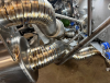
In the last post regarding the exhaust the 3.5” titanium cat-back system was tacked. Since then, Abe has finished approximately 1,242” of titanium welds. I need to decide if I’m going to:


- Leave them as is
- Remove the alpha case with a Scotch-Brite pad
- Remove the alpha case with a Scotch-Brite pad and heat them with a torch to obtain blue/purple colors
Attachments

Similar threads
- Replies
- 10
- Views
- 10K
- Replies
- 4
- Views
- 5K