
- Forums
- GT40 Replica Manufacturers' Corner
- RCR Forum - RCR40/SLC/917/Superlite Aero
- The SLC Clubhouse
You are using an out of date browser. It may not display this or other websites correctly.
You should upgrade or use an alternative browser.
You should upgrade or use an alternative browser.
SLC 24 Howard Jones
- Thread starter Howard Jones
- Start date
Howard Jones
Supporter
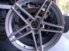
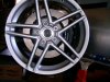
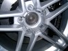
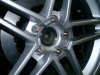
I started doing the homework to put on a set of two piece 13.06 X 1.25 Wilwood Rotors and I came across a set of ZO6 wheels. These are real GM, made in USA, wheels and were take offs. I got them delivered for right at 600 bucks so I couldn't pass them up. 9.5X18F and 12X19 rears. I have a set of black C6 8.5X18 and 10X19 that are excess. I will let them go cheap so let me know if anybody is interested. Real cheap guys!
I wanted to have the wheels in hand when I start trial fitting hats and making caliper mounts. I think the fronts will be a direct bolt on but the rears will require a radial mount caliper and a new mount. Since I want to avoid drilling any holes into the uprights I will use the existing mount points thus the homemade rear mounts.
When the hats, rotors, and calipers arrive I will post the progress.
Anyway, great set of wheels at a good price.
Attachments
Last edited:
")
Yeah Rob, but you guys are coming up with some unique and really neat stuff!
Making more work for me in the process. Keep it up please.
Finished rear window vents yesterday. "borrowed" Howard's shape for the upper ones
to resemble his scoop cutouts. Beat the mesh into submission for the shapes, looks good.
Making more work for me in the process. Keep it up please.
Finished rear window vents yesterday. "borrowed" Howard's shape for the upper ones
to resemble his scoop cutouts. Beat the mesh into submission for the shapes, looks good.
Howard,
Very cool build. Our new facility will be located in the east bay soon and it would be great to meet you.
Luke
Very cool build. Our new facility will be located in the east bay soon and it would be great to meet you.
Luke
Howard Jones
Supporter
Thanks, I watch your build page and wait until you get settled. Then maybe Rob and I can drop in. If you are on the other side of the bay drop in and say hello.
Thanks Howard!
That would be great. We will do a big BBQ and open house once we are settled. Hopefully we can get some other SLC owners out there for a photo shoot.
Cheers.
Luke
That would be great. We will do a big BBQ and open house once we are settled. Hopefully we can get some other SLC owners out there for a photo shoot.
Cheers.
Luke
Howard and Luke, This Cary McHugh. I am working on the pit crew for the QRP SLC. We call it the "Blue Mistress". I am also helping Rob with the wiring on his SLC. I'd love to come see what you have going on with your SLC Howard and Luke with the Lemans you guys are building up. I see the LeMans sitting in Ted's shop and wonder what it will look like when it is built. I'm in San Jose. Thanks guys.
Cary...the Le Mans is not the same as the LMP1....
Luke has an LMP and a diesel or two on their way too....
Not to mention a few other 4 wheeled machines being built for them at RCR too....
Luke has an LMP and a diesel or two on their way too....
Not to mention a few other 4 wheeled machines being built for them at RCR too....
Howard Jones
Supporter
Cary, PM me and I'll send you a ph # and address or ask Rob. If you guys want to come up together, cool. I think I need to lone/make new tube, Robert a tube bender anyway this week. Welcome anytime. Beer in Frig.
Sounds good guys. We will actually have 6 of our own SLC cars in the new shop pretty soon. I will keep you guys informed.
Cheers.
Cheers.
Howard Jones
Supporter
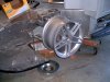
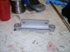
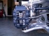
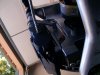
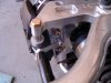
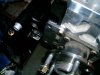
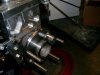
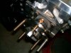
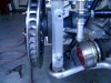
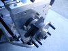
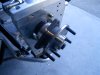
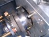
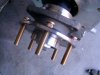
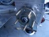
So here's the brakes. First one is bare upright with small notch relieved in bottom of caliper mount location. This is necessary if you do this. Not a big deal but you will need a high speed air tool and a cutting tool. Run at about a 25% full speed or you will burn up the tool. Take it easy. Maybe practice on some scrap aluminum.
The fronts are pretty easy. You could just mount the replacement rotor and hat and reuse the original caliper mount plate. I made a new one so that I could thread it and screw the caliper mount bolts in from the rear. These will need to be safety wired as well as the rest of the mounting hardware you see in these pictures.
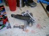
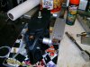
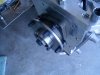
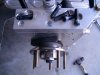
The rear is where I tool a little time. The next picture is the mistake pile. This is only the metal pieces I already threw away the cardboard and wood mock ups. The alum rear caliper mount in the pile was the washer fixture. I used this to just get the caliper close so that I could get some idea what I was doing. The steel piece was a first try that went bad.
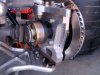
I should say this here. The caliper MUST be dead tits on square to the rotor and within a 32nd on radial location, and near perfectly centered so that the pad cavity's are EQUAL distance to the rotor face. REALLY! If you do this heed this paragraph.
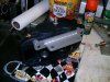
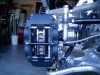
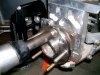
I made the pieces out of chrome molly. I like to work with it because it is very square dimensionally. It's also very strong. I used 1/4 strip so that when set on edge it will be square to the other piece it's being welded to. Pieces MUST be clamped together when welded work slowly and don't get the piece really hot. Keep covered between welds with a coffee can in still air to it won't crack. The stand offs came from McMaster car 3/4 X 3/4 with a 5/16 hole in the center. They are taped to receive the caliper bolts to 3/8-24 so the hole will need to be drilled out with a Q bit. Then I taped the complete piece through the plate. This gives about 1 inch of threads.
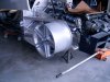
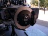
I used a 4 piston radial mount caliper in the rear because there just isn't enough room to mount a 12.88 inch diameter rotor with the mounting tab type caliper. This also allowed me to size the rear piston are to better suit the front calipers sizes and allow the use of two master of the same size. The rotors are 12.88 X 1.25 rear and 13.06 x 1.25 front.
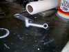
I also fixed the single shear toe link issue. These pieces were the most difficult parts to make because I had to jig them in place on the car. Lots of time here.
I will post a parts list and have made a drawing of the rear caliper mount but I don't know how to convert it to digital form.
The fronts are pretty easy. You could just mount the replacement rotor and hat and reuse the original caliper mount plate. I made a new one so that I could thread it and screw the caliper mount bolts in from the rear. These will need to be safety wired as well as the rest of the mounting hardware you see in these pictures.
The rear is where I tool a little time. The next picture is the mistake pile. This is only the metal pieces I already threw away the cardboard and wood mock ups. The alum rear caliper mount in the pile was the washer fixture. I used this to just get the caliper close so that I could get some idea what I was doing. The steel piece was a first try that went bad.
I should say this here. The caliper MUST be dead tits on square to the rotor and within a 32nd on radial location, and near perfectly centered so that the pad cavity's are EQUAL distance to the rotor face. REALLY! If you do this heed this paragraph.
I made the pieces out of chrome molly. I like to work with it because it is very square dimensionally. It's also very strong. I used 1/4 strip so that when set on edge it will be square to the other piece it's being welded to. Pieces MUST be clamped together when welded work slowly and don't get the piece really hot. Keep covered between welds with a coffee can in still air to it won't crack. The stand offs came from McMaster car 3/4 X 3/4 with a 5/16 hole in the center. They are taped to receive the caliper bolts to 3/8-24 so the hole will need to be drilled out with a Q bit. Then I taped the complete piece through the plate. This gives about 1 inch of threads.
I used a 4 piston radial mount caliper in the rear because there just isn't enough room to mount a 12.88 inch diameter rotor with the mounting tab type caliper. This also allowed me to size the rear piston are to better suit the front calipers sizes and allow the use of two master of the same size. The rotors are 12.88 X 1.25 rear and 13.06 x 1.25 front.
I also fixed the single shear toe link issue. These pieces were the most difficult parts to make because I had to jig them in place on the car. Lots of time here.
I will post a parts list and have made a drawing of the rear caliper mount but I don't know how to convert it to digital form.
Attachments
-
 HPIM1896.JPG175.3 KB · Views: 446
 -
 HPIM1905.JPG175 KB · Views: 388
 -
 HPIM1897.JPG148.2 KB · Views: 341
 -
 HPIM1898.JPG213.9 KB · Views: 339
 -
 HPIM1900.JPG204.9 KB · Views: 351
 -
 HPIM1903.JPG171.7 KB · Views: 341
 -
 HPIM1910.JPG176.2 KB · Views: 365
 -
 HPIM1908.JPG172.5 KB · Views: 332
 -
 HPIM1902.JPG153.6 KB · Views: 327
 -
 HPIM1901.JPG147.8 KB · Views: 348
 -
 HPIM1906.JPG158.7 KB · Views: 336
 -
 HPIM1907.JPG161 KB · Views: 304
 -
 HPIM1911.JPG203.6 KB · Views: 341
 -
 HPIM1894.JPG186.1 KB · Views: 343
 -
 HPIM1895.JPG189.3 KB · Views: 333
Last edited:
Way to go Howard, properly engineered as always. Too bad the toe link bracket could not have been more direct inline with the forces working upon it, but there is only so much one can do.
To the rest of you - Howard amazes me that he does this work with just basic shop tools. The trickest thing he has is the welder! All the more impressive.
To the rest of you - Howard amazes me that he does this work with just basic shop tools. The trickest thing he has is the welder! All the more impressive.
To the rest of you - Howard amazes me that he does this work with just basic shop tools. The trickest thing he has is the welder! All the more impressive.
and yet that's still 10x the amount of 'basic' shop tools that most of us have :laugh:
Howard Jones
Supporter
Ya, good catch Rob. I was able to pick up the for aft plane somewhat, but the inboard outboard plane just isn't do able. I tried to do that by putting as much angle as possible on the one link I did have. This really need two pickup points. If you used the hub mounting hex screws as a second mount point you could get at least another one.
You have no idea how long I looked at this. Had to go get more beer twice!
You have no idea how long I looked at this. Had to go get more beer twice!
Howard Jones
Supporter
These are Summit Racing part numbers, but they use Wilwood numbers after the prefix WIL.
You can look them up in the wildwood catalog if you leave off the WIL-
Rear
2 - Superlight 4 pot radial mount caliper 1.25 piston X 4 WIL 120-13232
1- HD Rotor 12.88 X 1.25, WIL-160-12784
1- HD Rotor 12.88 X 1.25, WIL-160-12785
2- Hat .290 offset, WIL-170-8919
Front
1- HD Rotor 13.06 X 1.25, WIL-160-12786
1- HD Rotor 13.06 X 1.25, WIL-160-12787
2- Hat .710 offset, WIL-170-10533
You will also need 48 grade 8, 1/4-20 X 1" socket head drilled screws (for safety wire) and four 3/4 X 3/4 X 5/16 steel standoffs. I got mine from McMaster Car.
Also Four 2.25 X 3/8 X 24 grade 8 socket head screws (caliper mount to adapter) From Fastenal.
These are also useful calculators for brake piston sizes and pedal pressure.
Dual Bias Calc.
Bias Calculator
These part numbers are only good for the guys with the original Wilwood brake package..
The OE brakes are now Brembo and have wider and larger rotors than Howards car was supplied with.
Just an FYI for anyone reading and wondering why Howard is doing his mod.
The reasoning behind the switch to Brembo was driven by overseas sales and world compliance , Wilwood calipers do not pass many countries brake compliance requirements , but the Brembos do....sorry for the brief hijack..
Howard Jones
Supporter
Fran is correct, we decided to leave the original brake package on the car when I ordered the kit because it was a place holder for me and didn't add any real cost to the purchase. I did use the front calipers however.
I should say that the original Wilwood 6 piston calipers and "corvette" aftermarket rotors would be fine for a street car IMHO. Secondly the presently as delivered base brake package is a very good one and if it had been available and on the my car I would not have changed it.
I can't afford Alcon's so this is what I came up with. Wilwood parts are a very cost effective way to outfit a very quick track day car. This system is designed to run 5, 30 mins sessions a day not long sprint races like Fran's car or endurance races of 6, 12 or 24 hour races.
Lastly be careful, clearances are good with my new setup but there is little margin for wheel clearances. I have about 5/16 to the nearest point inside of the wheels. My wheels are a OEM package GM corvette ZO6 set. I make no claim that others will fit this setup.
Howard Jones
Supporter
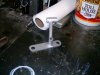
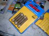
Wheels studs. Don't take the bearing apart or screw with it in any way! On either end of the car. It's not necessary!!!! You will frig it up! Here's how to install nice long studs.
The OEM studs are very marginal for length. They would have kept the wheels on......hopefully, but I am sure they would have gotten squawked in a Track Tech inspection.
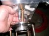
So I changed them with ARP studs that are 1 inch longer. The fronts were first and in the end I gave in and took a hammer to um. Well a little more careful than that. I used a wheel nut and a socket to hit on. I was concerned that I might drive the stud off center and this helps to direct the blow. Well it did for me. They came out pretty easy just a nice firm hit and then a couple of more and the splines cleared the hub face. Then the stud has enough room to push it out the back.
The new one goes in in reverse. Feed it through from the back using the cavity in the upright to increase clearance. I used motor oil on the splines and on the threads to prevent galling, then I put a thick washer between the hub face and a wheel nut and pulled it together with a 1/2 inch impact gun. This worked very well. Make sure you snug the wheel nut tight against the washer before you start with the impact gun and go very easy until the splines begin to seat. DO NOT SPIN THE SPLINES IN THE HUB FACE.
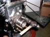
The rear was different but not really difficult. You will need to remove the CV joint from the stub axle, and loosen the three bolts that hold the hub on the upright. They DO have room but they all need to be loosened at the same time to allow the hub to be cocked in the upright. Leave the stub axel alone you don't need to screw with it. loosening the three bolts that hold the hub/stub axle on will get you clearance to remove them. once the three bolts are out you will have plenty of wiggle room to remove/install the wheel studs
Drive all the old wheel studs out of the hub face but leaving them loose in the hub first and when the hub is free from the upright they can be removed by angling the hub in the upright again. Now loosely place the all of the new studs in their holes from the back again, bolt the hub back in place in the upright, oil the studs and pull them into place with the impact gun like the front.
Done.
Note: You will ruin one wheel nut. You could use the proper METRIC bolt if you have one but I had several extra wheel nuts.
Note 2: The three METRIC socket head bolts that hold on the hub at the rear is very close on clearance. I cut off a short piece of allen wrench shaft from a 10mm drive socket and used a box end wrench to turn it, to get them out.
The OEM studs are very marginal for length. They would have kept the wheels on......hopefully, but I am sure they would have gotten squawked in a Track Tech inspection.
So I changed them with ARP studs that are 1 inch longer. The fronts were first and in the end I gave in and took a hammer to um. Well a little more careful than that. I used a wheel nut and a socket to hit on. I was concerned that I might drive the stud off center and this helps to direct the blow. Well it did for me. They came out pretty easy just a nice firm hit and then a couple of more and the splines cleared the hub face. Then the stud has enough room to push it out the back.
The new one goes in in reverse. Feed it through from the back using the cavity in the upright to increase clearance. I used motor oil on the splines and on the threads to prevent galling, then I put a thick washer between the hub face and a wheel nut and pulled it together with a 1/2 inch impact gun. This worked very well. Make sure you snug the wheel nut tight against the washer before you start with the impact gun and go very easy until the splines begin to seat. DO NOT SPIN THE SPLINES IN THE HUB FACE.
The rear was different but not really difficult. You will need to remove the CV joint from the stub axle, and loosen the three bolts that hold the hub on the upright. They DO have room but they all need to be loosened at the same time to allow the hub to be cocked in the upright. Leave the stub axel alone you don't need to screw with it. loosening the three bolts that hold the hub/stub axle on will get you clearance to remove them. once the three bolts are out you will have plenty of wiggle room to remove/install the wheel studs
Drive all the old wheel studs out of the hub face but leaving them loose in the hub first and when the hub is free from the upright they can be removed by angling the hub in the upright again. Now loosely place the all of the new studs in their holes from the back again, bolt the hub back in place in the upright, oil the studs and pull them into place with the impact gun like the front.
Done.
Note: You will ruin one wheel nut. You could use the proper METRIC bolt if you have one but I had several extra wheel nuts.
Note 2: The three METRIC socket head bolts that hold on the hub at the rear is very close on clearance. I cut off a short piece of allen wrench shaft from a 10mm drive socket and used a box end wrench to turn it, to get them out.
Attachments
-
 HPIM1918.JPG149.6 KB · Views: 338
 -
 HPIM1914.JPG175.9 KB · Views: 301
 -
 HPIM1913.JPG150.3 KB · Views: 308
 -
 HPIM1919.JPG224.3 KB · Views: 291
 -
 HPIM1915.JPG122.4 KB · Views: 291
 -
 HPIM1916.JPG133.7 KB · Views: 270
 -
 HPIM1917.JPG180.3 KB · Views: 273
 -
 HPIM1921.JPG160.1 KB · Views: 333
 -
 HPIM1931.JPG181.7 KB · Views: 283
 -
 HPIM1922.JPG151.9 KB · Views: 267
 -
 HPIM1924.JPG153.7 KB · Views: 264
 -
 HPIM1923.JPG148 KB · Views: 263
 -
 HPIM1928.JPG125 KB · Views: 296
 -
 HPIM1925.JPG159.8 KB · Views: 301
 -
 HPIM1930.JPG162.5 KB · Views: 273
 -
 HPIM1929.JPG161.8 KB · Views: 269
 -
 HPIM1920.JPG211.6 KB · Views: 366
Last edited:
Similar threads
- Replies
- 14
- Views
- 2K
- Replies
- 5
- Views
- 2K