Stephan's SLC Build Log

Stephan E.

Supporter
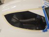
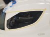
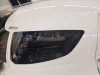
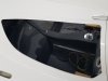
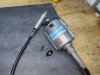
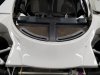
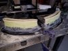
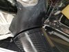
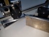
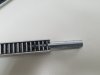
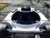
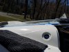
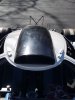
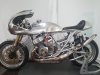
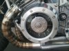
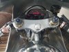
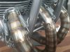
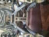
Last year in August I posted a few pictures of a the beginning of the build of a Bonneville Land Speed Record Bike. I am certain that what I posted was everything but convincing and probably to some, just hot air. The bike is done for three month and I thought I owe an update on what kept me sidetracked and away from the SLC. What you see here is a Kawasaki 1972 H2 750 that started as a bare frame and empty engine cases.
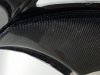
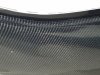
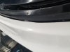
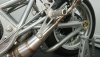
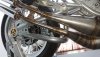
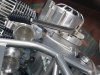
Stage 3 Drag Racing engine 160HP on 91 Octane at 9000 RPM with huge flat side carbs and I have no idea what it will do on race gas or with NOS. Ducati racing dry clutch in one-off billet casing to transfer the power going through an undercut racing transmission. HP and max torque set in 300 RPM apart at around 6000 RPM and is like the ON switch to unleash hell. That is when you have to tuck in your balls, hold on to the dentures and make sure the underwear is absorbent. Reinforced frame and swing arm of my own design and fabrication, equipped with the biggest brakes on the market. All custom coachwork, stainless chambers, all digital electronics and street legal in PA :cool:. An insanely fast lightweight and dangerous at any speed. Someday I will put it in a trailer and just go after that Speed Demon...
 

Attachments

  • 20220425_174750.jpg
    20220425_174750.jpg
    406.5 KB · Views: 405
  • DSC_0902.JPG
    DSC_0902.JPG
    347.2 KB · Views: 386
  • DSC_0903.JPG
    DSC_0903.JPG
    346.9 KB · Views: 237
  • 20220416_121740.jpg
    20220416_121740.jpg
    466.7 KB · Views: 228
  • 20220610_173413.jpg
    20220610_173413.jpg
    379.5 KB · Views: 212
  • 20220424_092540.jpg
    20220424_092540.jpg
    345 KB · Views: 204
  • 20220129_093023.jpg
    20220129_093023.jpg
    378.2 KB · Views: 212
  • 20220408_072141.jpg
    20220408_072141.jpg
    523.8 KB · Views: 275

Randy V

Moderator-Admin
Staff member
Admin
Lifetime Supporter
Amazing work! Your marble-bag is definitely bigger than mine!
@manta22 needs to see this post.. He does Bonneville with his car….
 

Stephan E.

Supporter
Chipping away little by little... Continuing on the doors. Cleaned up the factory door window pre-cut outs for maximum visibility and a cleaner look. I don't use sharp corners and cut radii instead with a hole saw to prevent stress risers.
 

Attachments

  • 20220702_104128.jpg
    20220702_104128.jpg
    189.4 KB · Views: 327
  • 20220702_104140.jpg
    20220702_104140.jpg
    192.1 KB · Views: 247
  • 20220703_102928.jpg
    20220703_102928.jpg
    211.9 KB · Views: 229
  • 20220723_183912.jpg
    20220723_183912.jpg
    205.9 KB · Views: 259

Stephan E.

Supporter
Spent some time with trimming and installing the carbon fiber door cards in preparation to fit the dash. It took and minute or two to get those properly fitted. On mine, the factory pre-cut left me with a huge gap to adjust. I started with a 6mm (1/4") distance from the door card to the inner door profile and was not sure where to start. The inner door profile is over 1 Meter (43") along the window, changes directions and constantly curves from the dash to the upper window edge. A job that can not be rushed and if you take too much material off you a screwed since the carbon fiber can not be patched. 3 hours later it was done and now they fit along the entire inner doors just perfectly. The pictures can not judge. I am not a friend of sheet metal screws in fiberglass und use decent hardware such as rivet nuts.
 

Attachments

  • 20220730_103512 (2).jpg
    20220730_103512 (2).jpg
    222.1 KB · Views: 221
  • 20220724_101725.jpg
    20220724_101725.jpg
    398.8 KB · Views: 223
  • 20220730_184935.jpg
    20220730_184935.jpg
    332.9 KB · Views: 217
  • 20220730_185205.jpg
    20220730_185205.jpg
    410 KB · Views: 216
  • 20220730_185531.jpg
    20220730_185531.jpg
    294.1 KB · Views: 209
  • 20220730_185536.jpg
    20220730_185536.jpg
    440.9 KB · Views: 224

Stephan E.

Supporter
Nice work Stephan, what tool(s) did you use to trim them down?
Hello Joel,

I am using the abrasive wheel cutting tool in the picture with Fiberglass, especially when Gelcoat is applied. The strong motor is consistent and gives you excellent control over the cut. Similar to a Dremmel but much stronger and the brushless motor does not heat up. I don't use any reciprocating tools such as hacksaw, jigsaw etc. at all to prevent chipping or delamination. In addition a good fine file set which I only use in the direction of the Gelcoat and never against it. A time robbing process but the outcome is worth it.
 

Attachments

  • 20220731_101740.jpg
    20220731_101740.jpg
    551.2 KB · Views: 222

Stephan E.

Supporter
Moving forward with the dashboard. On that subject I'll have more than one posting. The first thing I noticed was that the material thickness under the windshield on my car was very inconsistent and created a bumpy surface resulting in the dash to not fit that area very well. After reworking that the profile a much better fit. Next thing I was wondering about is on how to support that dash. From other builds I learned that bonded or bolted brackets and standoffs seem to be the way to go but I did not consider it for my build. I took a second look at the factory ducts and dash underside and decided that I'll use that as support by making a mold from the dash and apply it to the 50mm extended ducts. The dash is now supported over more than 26" instead of single point supports. The dash drops on the vent molds just before it hits the curve. It took some time to figure out the correct height but eventually I got there. The door cards determine the height of the dash facing the driver and passenger, creating a reference and demanding proper transition. When the dash was inserted it shifted to the left quite a bit. This is determined by the curved profile of the windshield. Everything I measured and believed when initially fitted the dash without the body, is down the drain. The dash is matching the door nicely on the driver side but I am missing 10 - 12mm on the passenger door. I read a few posts and must have looked at least at 25 - 30 sets of SLC interiors to get a better understanding on how to fit that dash. All the ones I found have an offset to the left and none that I found had a centered steering wheel in relation to the gauges so my car does the same thing. Giving it a moment to sink in I started to like that situation. I'll need to remove the steering offset by modifying the linkage, get the column center and straight and I'll be able to shift my seat to the left, make room for the rear seat anchors inboard and no angled seat. I am glad that I have not installed my seats yet. Here are a few pictures of the current progress.
 

Attachments

  • 20220723_173627.jpg
    20220723_173627.jpg
    176.5 KB · Views: 234

Stephan E.

Supporter
More pictures, I hit the button to early:rolleyes:
 

Attachments

  • 20220723_092355.jpg
    20220723_092355.jpg
    451.2 KB · Views: 219
  • 20220723_173025.jpg
    20220723_173025.jpg
    504.7 KB · Views: 213
  • 20220723_173048.jpg
    20220723_173048.jpg
    431.2 KB · Views: 219
  • 20220731_135245.jpg
    20220731_135245.jpg
    351.8 KB · Views: 216
  • 20220731_135310.jpg
    20220731_135310.jpg
    287.2 KB · Views: 214
  • 20220724_172535.jpg
    20220724_172535.jpg
    191.8 KB · Views: 211
  • 20220731_101632.jpg
    20220731_101632.jpg
    413.2 KB · Views: 273

Johan

Supporter
Moving forward with the dashboard. On that subject I'll have more than one posting. The first thing I noticed was that the material thickness under the windshield on my car was very inconsistent and created a bumpy surface resulting in the dash to not fit that area very well. After reworking that the profile a much better fit. Next thing I was wondering about is on how to support that dash. From other builds I learned that bonded or bolted brackets and standoffs seem to be the way to go but I did not consider it for my build. I took a second look at the factory ducts and dash underside and decided that I'll use that as support by making a mold from the dash and apply it to the 50mm extended ducts. The dash is now supported over more than 26" instead of single point supports. The dash drops on the vent molds just before it hits the curve. It took some time to figure out the correct height but eventually I got there. The door cards determine the height of the dash facing the driver and passenger, creating a reference and demanding proper transition. When the dash was inserted it shifted to the left quite a bit. This is determined by the curved profile of the windshield. Everything I measured and believed when initially fitted the dash without the body, is down the drain. The dash is matching the door nicely on the driver side but I am missing 10 - 12mm on the passenger door. I read a few posts and must have looked at least at 25 - 30 sets of SLC interiors to get a better understanding on how to fit that dash. All the ones I found have an offset to the left and none that I found had a centered steering wheel in relation to the gauges so my car does the same thing. Giving it a moment to sink in I started to like that situation. I'll need to remove the steering offset by modifying the linkage, get the column center and straight and I'll be able to shift my seat to the left, make room for the rear seat anchors inboard and no angled seat. I am glad that I have not installed my seats yet. Here are a few pictures of the current progress.
Nice work Stephan, I did it pretty much the same exept the other way around. I extended the dash around the cut outs to reach the duct and then some bulb seals.
 

Kyle

Supporter
Have you sat in the car with the door cards on? I really don’t know how anyone drives with them, it’s tight as is.
 

Stephan E.

Supporter
Have you sat in the car with the door cards on? I really don’t know how anyone drives with them, it’s tight as is.
Hello Kyle,

I just sat in the car yesterday after the corrected steering column position toward the left and did not get the impression that is it is too tight for me. I can only speak for myself. I am 5'11" at 185 Lbs, so not the biggest guy, using Tillet B5s. Plenty of room on the left side for shoulder and arm. My passenger may has a different opinion since there is 2" less room to mount the seat. In my opinion the door cards are really a nice touch to the spartan SLC interior.
 

Stephan E.

Supporter
The dash did not align with the door card on the passenger side while it almost perfectly gaped with the card on the left door. Found pics of other SLCs with the same issue. Unfortunately the owners did not make the correction which I can totally understand because it is just another P.I.T.A. The dash was cut and extended by 13mm, reinforced and then recontoured. Now both sides are now equal. Next step is to build and contour the dash to the forward door frames.
 

Attachments

  • 20220806_163231.jpg
    20220806_163231.jpg
    371.8 KB · Views: 206
  • 20220806_163045.jpg
    20220806_163045.jpg
    389.2 KB · Views: 206
  • 20220806_165930.jpg
    20220806_165930.jpg
    357.2 KB · Views: 202
  • 20220807_133135.jpg
    20220807_133135.jpg
    374 KB · Views: 199
  • 20220812_170500.jpg
    20220812_170500.jpg
    345.3 KB · Views: 231

Stephan E.

Supporter
Back on the doors. I pulled my actuators out and looked at Alan's videos and numerous SLC pictures with automatic doors. I am sure this was already though of by someone else or previously done in a similar way but it seems that the actuator installations could use some more detailed posts. At first I was a little concerned about the weight of the actuators and the insulation materials for the doors combined on top the huge cutout to be made to cover the actuator rod travel and the required space for the bracket penetrating into the lower door sections. I tackled one problem at the time with the weight first. How much of everything do you actually need I asked myself. The result was a shorter bracket. I used 4" x 3" instead and sat the actuator flat on the horizontal surface of the angle. That required the pivot to move 20mm since I am using a shoulder bolt with large washer with self locking nut. This has no effect on the travel of the angle at all. I shortened the bottom plate by an inch which also now served as a threaded point to one of the door card screws, disassembled the actuators to put them on a diet by removing as much material as I could including the back of the angle. The self lubrication plastic is now only 1/8" instead of 1/4". I drilled and taped the rails but will not use threaded end rods. Instead I am using a stud that will be threaded to the required length and then thread on a female end rod with a lock nut. I don't like the skinny appearance of extended rods to get the doors into the vertical position besides the fact that end rods with extended shanks are are a rare find. The result is that the cutout in the door now smaller from what I have previously seen since the entire package is sitting lower. Everything is installed and working perfectly. I'll cover that with the next post.
 

Attachments

  • 20220905_173352.jpg
    20220905_173352.jpg
    204.5 KB · Views: 186
  • 20220905_173401.jpg
    20220905_173401.jpg
    195.2 KB · Views: 181
  • 20220905_173421.jpg
    20220905_173421.jpg
    209.9 KB · Views: 186
  • 20220907_140516.jpg
    20220907_140516.jpg
    307.6 KB · Views: 170
  • 20220907_154510.jpg
    20220907_154510.jpg
    269.8 KB · Views: 163
  • 20220907_154821.jpg
    20220907_154821.jpg
    207.1 KB · Views: 243

Stephan E.

Supporter
The original airduct had to be sacrificed for something more efficient to feed the animal housed in the back. Cold air of large quatities has to be provided and to accomodate the velocity stacks sticking out of the rear clam. Took a moment to find the countour and proportions to make use of all available space and still to find an anaesthetically pleasing solution that will give the SLC and completely new stance. Still a ton or of work to do but it will look awesome when finished.
 

Attachments

  • 20230326_104332 (3).jpg
    20230326_104332 (3).jpg
    467.8 KB · Views: 181
  • 20230326_122011.jpg
    20230326_122011.jpg
    437.1 KB · Views: 188
  • 20230326_095850 (2).jpg
    20230326_095850 (2).jpg
    230.2 KB · Views: 193
Last edited:

Stephan E.

Supporter
Over the past winter month, I was thinking about the emergency door release for my automatic doors and reviewed what other builders had invented or thought of, came up with, tested and where they had succeeded or failed. It is certainly a vital function for when power failed or the actuator jammed, controller running amok etc. Of course, I looked at the pulled pin versions and the trapped pin with quick release. Made them and tried them all. Nothing convinced to safely work when needed or did not provide all features I wanted. On my list was for such mechanism was

• Safe against accidental release from hitting, pulling, bumping, and stepping on it.
• Provides an actuator overload protection that can be adjusted as needed.
• The release mechanism inside the cabin can be concealed or neatly integrated and is accessible when needed.
• It fits in the existing space between body and door,

In the pictures is the prototype of a completely new idea for an actuator release. I took my blinders off and looked at other places to disconnect the actuator. Instead of using the pin as the location for the separation I separate the bracket from the body. It is mounted to a saddle with 45-degree angles, clamped into a machined aluminum block. The block is spring loaded, and the saddle will pop out of the block to release when the actuator pull would exceed the pre-load. I am currently testing various springs and bracket types to see what is best. The manual (emergency) release will be by a turning hand knob. The final version will be all cleaned up and painted when done.
 

Attachments

  • 20230326_183152.jpg
    20230326_183152.jpg
    555.4 KB · Views: 122
  • 20230326_183414.jpg
    20230326_183414.jpg
    452.9 KB · Views: 115
  • 20230326_184246.jpg
    20230326_184246.jpg
    440.7 KB · Views: 110
  • 20230330_192147.jpg
    20230330_192147.jpg
    178.2 KB · Views: 118
Looks like a potential alternative option, very clean design. To play devil's advocate, how many rotations of the knob are required to have it release? ie in an accident, wrist injury, fuel pouring out, fire, etc. Just make sure it is something quick and thoughtless.
 

Stephan E.

Supporter
Hello Dave,

Like with any design there is no guarantee to properly open if the driver or passenger can not operate the release. I have tested with 1.5mm pitch which releases after 2 turns. Final setting will depend on the ergonomics of the lever or handheld I will use. Changing the ratio is simply replacing the Helicoil inside the clamping base and a threaded rod with corser pitch.
 
Back
Top