You are using an out of date browser. It may not display this or other websites correctly.
You should upgrade or use an alternative browser.
You should upgrade or use an alternative browser.
Dr. Bob Woods
Supporter
Mounting of Fans on a Radiator
There are two ways to mount fans on a radiator: mount the fan directly to the radiator, or build a shroud to hold the fan a short distance away from the surface of the radiator.
If you mount the fan directly to the radiator, it is normally done with plastic ties that are pushed through the fins and coils of the radiator. This seems to be an undesirable technique in itself since it will deform the fins, and with the vibrations of the fan and vehicle, it might eventually wear through the coils and cause a leak or flatten the fins. The second problem is that the fan blades are literally next to the radiator fins which will cause a large flow degradation compared to running the fan in free air. Further, the air will only pass through the area below the fan blades and the air distribution is not uniform across the area of the fan since there will be no flow at the center of the fan. Thus, only a small area of the radiator has air flow through it.
If you mount the fan on a shroud to create a plenum behind the fans, then the fan blades are not next to the radiator fins and hence act more like it was in free air. The fan will pull a vacuum over the entire area of the shroud and will hence have a more uniform flow over the entire area, and that area will be larger than the area below the fan blades. Based on this reasoning, it appears that the shroud mounting would be the clear solution; however, I have tested the various combinations of mounting techniques and radiator flow on a flow bench to verify this assumption.
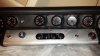
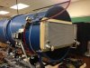
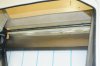
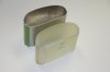
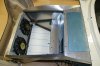
We have a large flow bench that can provide substantial flow to a test section. The first test was to measure the pressure-flow characteristics of the fan mounted on a flat plate with a circular opening as shown by the first photo. This gave us the free flow characteristics of an individual fan. Since there will be two fans, we can double the flow measurement with no increase in pressure to get what the ideal flow from two fans would be in free air.
A pressure-flow curve for the fan can be generated by turning the fan on and providing a variable restriction upstream of the fan to get a progression from the blocked pressure (with the valve closed) and a maximum flow (with the valve open).
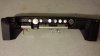
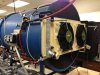
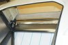
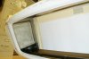
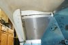
The next test was with the radiator mounted to the test section as shown by the second photo. We can generate a pressure-flow curve by varying the speed of the flow bench pump.
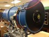
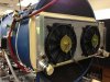
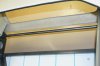
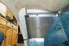
The fans were then connected directly to the radiator as shown by the next picture.
Finally, a shroud was built that encompassed the entire radiator surface (in two parts) with fans mounted to the shroud.
First of all, consider the free flow pressure drop across the radiator with no fans. As shown in the graph, it has a pressure drop of 0.30 inches of water at 1000 cfm. When the fans are mounted directly to the radiator (but turned off), the pressure drop increases to 0.38 inches of water. You might think that the shroud would cause a large restriction to free flow; however, the shroud with fans attached (but turned off) only increases the pressure drop to almost 0.40 inches of water.
Next consider the air flow with the fans turned on. From the test of a single fan and then doubling the flow, we can see that the ideal maximum free air flow of the fan is the top red line ranging from 0.60 inches of water to well over 1400 cfm. When the fans are mounted directly on the radiator and turned on the pressure and flow ranges from 0.20 inches of water to 600 cfm. When the fans are mounted on the shroud and turned on the pressure and flow ranges from 0.50 inches of water to 900 cfm.
The intersection of the fan and radiator curves illustrate the actual operating point. For the fans mounted directly on the radiator, the actual flow will be about 350 cfm. When the fans are mounted on the shroud the flow will be about 530 cfm. Even though this is a 50% increase in flow, it is actually a much larger increase in cooling effect since the fans mounted directly on the radiator only have a small area of air flow through the fan and hence do not cool as much water as a uniform flow over the entire area of the radiator. Thus, it is clear that the shroud will provide much better cooling.
I will build an angled shroud that has the stand-off to the bottom of the radiator larger than the top. This will give more volume in the shroud’s plenum and will direct the flow more upward and into the nostrils better. I will further mount the fans with some sort of vibration isolation so they won’t make so much noise. I will post a photo of this when I get it built.
-Bob Woods
There are two ways to mount fans on a radiator: mount the fan directly to the radiator, or build a shroud to hold the fan a short distance away from the surface of the radiator.
If you mount the fan directly to the radiator, it is normally done with plastic ties that are pushed through the fins and coils of the radiator. This seems to be an undesirable technique in itself since it will deform the fins, and with the vibrations of the fan and vehicle, it might eventually wear through the coils and cause a leak or flatten the fins. The second problem is that the fan blades are literally next to the radiator fins which will cause a large flow degradation compared to running the fan in free air. Further, the air will only pass through the area below the fan blades and the air distribution is not uniform across the area of the fan since there will be no flow at the center of the fan. Thus, only a small area of the radiator has air flow through it.
If you mount the fan on a shroud to create a plenum behind the fans, then the fan blades are not next to the radiator fins and hence act more like it was in free air. The fan will pull a vacuum over the entire area of the shroud and will hence have a more uniform flow over the entire area, and that area will be larger than the area below the fan blades. Based on this reasoning, it appears that the shroud mounting would be the clear solution; however, I have tested the various combinations of mounting techniques and radiator flow on a flow bench to verify this assumption.
We have a large flow bench that can provide substantial flow to a test section. The first test was to measure the pressure-flow characteristics of the fan mounted on a flat plate with a circular opening as shown by the first photo. This gave us the free flow characteristics of an individual fan. Since there will be two fans, we can double the flow measurement with no increase in pressure to get what the ideal flow from two fans would be in free air.
A pressure-flow curve for the fan can be generated by turning the fan on and providing a variable restriction upstream of the fan to get a progression from the blocked pressure (with the valve closed) and a maximum flow (with the valve open).
The next test was with the radiator mounted to the test section as shown by the second photo. We can generate a pressure-flow curve by varying the speed of the flow bench pump.
The fans were then connected directly to the radiator as shown by the next picture.
Finally, a shroud was built that encompassed the entire radiator surface (in two parts) with fans mounted to the shroud.
First of all, consider the free flow pressure drop across the radiator with no fans. As shown in the graph, it has a pressure drop of 0.30 inches of water at 1000 cfm. When the fans are mounted directly to the radiator (but turned off), the pressure drop increases to 0.38 inches of water. You might think that the shroud would cause a large restriction to free flow; however, the shroud with fans attached (but turned off) only increases the pressure drop to almost 0.40 inches of water.
Next consider the air flow with the fans turned on. From the test of a single fan and then doubling the flow, we can see that the ideal maximum free air flow of the fan is the top red line ranging from 0.60 inches of water to well over 1400 cfm. When the fans are mounted directly on the radiator and turned on the pressure and flow ranges from 0.20 inches of water to 600 cfm. When the fans are mounted on the shroud and turned on the pressure and flow ranges from 0.50 inches of water to 900 cfm.
The intersection of the fan and radiator curves illustrate the actual operating point. For the fans mounted directly on the radiator, the actual flow will be about 350 cfm. When the fans are mounted on the shroud the flow will be about 530 cfm. Even though this is a 50% increase in flow, it is actually a much larger increase in cooling effect since the fans mounted directly on the radiator only have a small area of air flow through the fan and hence do not cool as much water as a uniform flow over the entire area of the radiator. Thus, it is clear that the shroud will provide much better cooling.
I will build an angled shroud that has the stand-off to the bottom of the radiator larger than the top. This will give more volume in the shroud’s plenum and will direct the flow more upward and into the nostrils better. I will further mount the fans with some sort of vibration isolation so they won’t make so much noise. I will post a photo of this when I get it built.
-Bob Woods
Attachments

Very interesting stuff, and seems to validate what the OEMs have been doing for years- building shrouded fans for better efficiency.
I would guess that shroud design also has a significant affect on the tests as well. I've seen flat shrouds that look like they would be marginal at the edges, and were probably made that way for ease of fabrication, as opposed to optimal flow characteristics. The OEM shrouds I've examined all show evidence of careful design around the edges, as well as some consideration for the volume of the shroud, as well as careful attention to sealing to minimize air leakage.
My SLC has a homemade CF shroud with good edge sealing, a decent blade offset from the rad body, and what I hope is good airflow at the edges as well as directly under the fan blades.
It would be interesting to test different shroud designs in your test harness to validate assumptions about shroud volume overall and at the edges, as well as single large vs 2 small fans, etc.
Great work on the actual testing of these fans and shrouds!
Terry Oxandale
Skinny Man
Great contribution Bob. I always wondered if I was hindering cooling performance (considering the fans only operate in slow or stopped vehicle speed) with the shroud I built, but your analysis indicates overall, it was the wise choice. Any intuitive thoughts on the effects of shroud depth vs efficiency, and at what point the reduction of it becomes significant. I would think the deeper, the more uniform the core-area flow through the radiator would be, but at some point I would think increasing the depth further has diminishing returns; and decreasing it to some value starts reducing that uniform flow significantly and quickly.
Thanks!

Thanks!
Last edited:
Keith Stafford
Supporter
Interesting stuff Bob, what minimum distance would you recommend for the distance between the fan (on a shroud) and the radiator? K
Dr. Bob Woods
Supporter
Thanks guys, I enjoyed doing it. The foam-core shrouds that I made for the test were 0.5 inches at the top and 1.5 inches at the bottom. I plan to make my aluminum shroud about 1 inch at the top and 3 or 3.5 inches at the bottom. That will help angle the fans better into the nostrils and give me more plenum volume.
I have tested a relatively small shroud (1 inch extended) on a small (~12"x14") radiator in our Formula SAE car and then installed a shroud with a larger volume (2 inch extended). We did get more flow through the larger plenum by a few percent. I suspect that there will be diminishing returns for larger plenums.
I do plan to seal the shroud around the edges and around the fan housing as well as putting some sort of vibration isolation in the mounting.
I will retest when I get the aluminum shroud made and I can then test an increased plenum volume at that time.
The real limit is clearance of the nostrils. I have extended my nostrils (I will post that soon) and I don't have a lot of clearance between the nostril splitter and the shroud.
-Bob Woods
Dr. Bob Woods
Supporter
Air Flow in Front of the Radiator and Brake Ducts
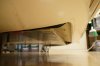
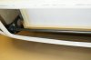
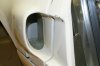
As I look at the layout of the body parts in front of the radiator, it is clear that the air has an open path to go underneath the radiator and to the sides without much restriction. The first photo illustrates the opening in the front of the radiator at the bottom. Keep in mind that the radiator is angled which will help the air go underneath.
Shown in the first photo is the gap at the bottom front of the radiator viewed from the front with the front clip closed and the radiator installed (there is a white cardboard protective cover over fins).
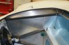
The second photo is the gap in front of the radiator viewed from inside the front clip with the clip open and the radiator removed. You can see the tan floor in the gap between the front of the chassis where the floor is attached and the swivel rod that articulates the front clip.
The next photo shows the aluminum extension that I fabricated to seal most of the opening. It overlaps the floor 1” and extends to the swivel rod for the front clip. I put a 90 degree bend in it for stiffness, but that also touches the fiberglass piece that attaches to the front clip in the next photo.
The fiberglass piece will be attached (fiberglassed) to the curved lip on the back of the radiator opening in the front clip and is held in place with Adel clamps on the swivel rod shown in the next photo.
The next photo shows the view from the bottom illustrating the floor extension and the fiberglass seal.
These two additions effectively seal the bottom of the front of the radiator. Next is to reduce the flow to the two sides of the radiator. To do this, I fabricated extensions to the vertical side openings on the front of the clip. I made molds and the fiberglass parts. In addition to blocking some of the lateral flow it also starts a duct that can direct air to the front brakes (although right now I don’t plan to do anything else with them).
The other advantage of these extensions to the opening is that it makes it look more finished to see a duct instead of seeing the ground. Clayton did something similar.
I did the same thing for the cooling inlets for the engine and brakes on the rear clip.
This was a lot of mold making and fiberglass work, but I think it will be worth it in the finished product, and I think my cooling will be very effective with this and the addition of the radiator shroud and the modified nostrils.
-Bob Woods
As I look at the layout of the body parts in front of the radiator, it is clear that the air has an open path to go underneath the radiator and to the sides without much restriction. The first photo illustrates the opening in the front of the radiator at the bottom. Keep in mind that the radiator is angled which will help the air go underneath.
Shown in the first photo is the gap at the bottom front of the radiator viewed from the front with the front clip closed and the radiator installed (there is a white cardboard protective cover over fins).
The second photo is the gap in front of the radiator viewed from inside the front clip with the clip open and the radiator removed. You can see the tan floor in the gap between the front of the chassis where the floor is attached and the swivel rod that articulates the front clip.
The next photo shows the aluminum extension that I fabricated to seal most of the opening. It overlaps the floor 1” and extends to the swivel rod for the front clip. I put a 90 degree bend in it for stiffness, but that also touches the fiberglass piece that attaches to the front clip in the next photo.
The fiberglass piece will be attached (fiberglassed) to the curved lip on the back of the radiator opening in the front clip and is held in place with Adel clamps on the swivel rod shown in the next photo.
The next photo shows the view from the bottom illustrating the floor extension and the fiberglass seal.
These two additions effectively seal the bottom of the front of the radiator. Next is to reduce the flow to the two sides of the radiator. To do this, I fabricated extensions to the vertical side openings on the front of the clip. I made molds and the fiberglass parts. In addition to blocking some of the lateral flow it also starts a duct that can direct air to the front brakes (although right now I don’t plan to do anything else with them).
The other advantage of these extensions to the opening is that it makes it look more finished to see a duct instead of seeing the ground. Clayton did something similar.
I did the same thing for the cooling inlets for the engine and brakes on the rear clip.
This was a lot of mold making and fiberglass work, but I think it will be worth it in the finished product, and I think my cooling will be very effective with this and the addition of the radiator shroud and the modified nostrils.
-Bob Woods
Attachments
-
 underside of radiator seal.jpg80 KB · Views: 1,081
 -
 opening sealed with fiberglass piece.jpg108.1 KB · Views: 972
 -
 opening partiall sealed with extend floor.jpg102 KB · Views: 976
 -
 Openiing in front of radiator viewed from behind front clip.jpg101.7 KB · Views: 1,028
 -
 original gap in front of radiator with front clip closed.jpg79.1 KB · Views: 1,138
 -
 inlet mold.jpg53.9 KB · Views: 1,016
 -
 front brake inlet installed.jpg91.6 KB · Views: 1,011
 -
 rear scoop installed.jpg105.9 KB · Views: 1,193
 -
 rear scoop from inside.jpg110.1 KB · Views: 1,193
Terry Oxandale
Skinny Man
Nice work. These little details will show up in improved slow-speed cooling, and in the ram effect's ability to force more air through the radiator at speed. Ducting in front is just as important as in back (the shroud) in order to create a closed path of air flow through the radiator and fans.
Dr. Bob Woods
Supporter
Air Flow on the Back Side of the Radiator
Now that I have somewhat sealed the front of the radiator to help push the air flow through the radiator (see my post # 130), it is time to consider the back side of the radiator to help pull the air through the radiator.
One of the lowest pressure (highest vacuum) points on the car occurs just before the nostrils on the front clip. The slight rise at the front of the nostril acts as a Gurney flap and reduces the pressure even more. Therefore there is a very low pressure region over the nostrils which will put a low pressure on the back side of the radiator when the car is driving. The pressure in the wheel wells is higher than the pressure in the bay area under the front clip.
To take advantage of the low pressure through the nostrils, the bay area under the front clip needs to be sealed on the sides. If this area is left open, then the vacuum in the nostrils will suck the higher pressure air in the wheel area into the front bay area instead of pulling the air through the radiator. Therefore, I want to seal the front bay area so the vacuum in the nostrils can only pull air through the radiator.
To do this, I put a panel on the vertical side opening defined by the steel chassis to block the air flow from the wheel well to the back side of the radiator. This was not specified in the Tornado assembly manual. In addition to that, I attached an aluminum lip to go from the chassis upward to the front clip as shown in the photos. This aluminum lip comes close to the front clip but does not touch it. Now the front bay area is sealed from the wheel well area and the nostrils will suck air through the radiator more effectively. Note that the fan position in this photo is a left over from the air flow bench testing (post # 124, third picture) and is not in the correct position. I will finish the fan shroud later.
Sealing the Wheel Wells
Even neglecting the advantages for cooling the radiator, I want to seal the front bay area to prevent water and dust coming from the wheel well to go into the front bay. I hope I don’t have to drive in the rain; but if I do, having the wheel well area open will allow water to get into the front bay and possibly go back to the driver compartment and get the carpet wet.
Further, it will be a mess to clean up and if I continue with the highly polished aluminum panels provide by Tornado and will scratch them.
A fiberglass seal was placed on the foot of the front clip to block water and debris from going from the wheel well area straight back to the top of the sills (and hence potentially draining to the carpets). The other advantage of this seal is that it adds stiffness to the foot and blocks some road noise.
I placed another fiberglass piece laterally across the top of the front clip near the fuel caps to stop water, dust, and noise from going past the wheel well area. I then put a rubber strip on the chassis to seal the gap between the added fiberglass pieces and the chassis.
This was a lot of extra work, but I think it is appropriate and will be effective in cooling and sealing the wheel well from water, dust, and noise.
-Bob Woods
Attachments
Bob,
The DRB's come with most of the pieces you are fabricating. You will notice a great improvement of radiator temps with the additions you are doing. Thew most important benefit to me is the lack of dust and dirt in that area. It is a bitch to clean. The only area I have to pay attention to is the area just in front of or below the radiator area(my radiator is at a steep angle which allows me to have a bigger radiator). You will be amazed at how dirty that area gets. That is the amount of dirt and oily debris that would have gotten in the bay area. Surprisingly my wheel wells have stayed very clean.
The one item I haven't added is the dam on the sill area. I plan on adding it to help set the correct height of the rear front clip. I will probably add some Dzus fasteners to that piece as well even though that is a high pressure area. My winter projects list is getting longer and longer!!!
Bill
Dr. Bob Woods
Supporter
Anthony,
I don't know what it is. I bought it as a part of my full Tornado package. I don't think it is Vintage Air because it doesn't have any logo on it that I remember and it doesn't look like anything called Vintage Air online. It seems to be a nice unit having both heating and cooling and fits nicely under the dash. You might ask Andy at Tornado.
Bill,
Thanks for the confirmation and discussion.
-Bob Woods
I'll try to take a photo or two of mine for you to compare with it you want Bob. I have the Vintage Air Gen II Mini. There is a Rod Shop in Sachse where I buy all my parts from (although you may be good for all of them as you got it in a complete kit).
I think the Vintage Air Gen II Mini is what most folks here suggested. It fits, but just barely. I ended up putting it on the passenger (left side in the US) side as high up as I could get angled at about a 45 degree angle. I was hoping the whole thing would fit parallel with the dash but with everything else there, the wiper motor, etc., I just couldn't get it in that spot without angling.
I think the Vintage Air Gen II Mini is what most folks here suggested. It fits, but just barely. I ended up putting it on the passenger (left side in the US) side as high up as I could get angled at about a 45 degree angle. I was hoping the whole thing would fit parallel with the dash but with everything else there, the wiper motor, etc., I just couldn't get it in that spot without angling.
The Mini is what I have. I had it mounted for a while and then decided to take it out when I started the wiring. It fit nice and square in the center of the dash, but then I didn't put wipers in. I don't plan on driving in the rain. Had the compressor mounted on the engine, but never got around to running the lines. Have found some alternatives that work well. Super insulation. In the late fall I put the side windows on and I stay comfortable. In the summer I take them off and the slight breeze at all speeds keeps me from sweating. Drove the car up to Gainesville(aprox 60 miles) to get the final tune and it was 28 degrees out and my garage was low 50s. With a light jacket I was comfortable for the entire trip. It isn't 100% air tight so there are some air exchanges.
Bill
Bill
Dr. Bob Woods
Supporter
Clayton,
Thanks for the feedback. I would be interested in more observations you might have such as dust coming from the wheel well, wind noise, heat in cockpit, visibility, driving on the streets, etc. so I can do something about it now. Any suggestions?
-Bob Woods
Thanks for the feedback. I would be interested in more observations you might have such as dust coming from the wheel well, wind noise, heat in cockpit, visibility, driving on the streets, etc. so I can do something about it now. Any suggestions?
-Bob Woods
Dr. Bob Woods
Supporter
Paint Color
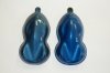
I have been struggling with the choice for my color for more than a year. I originally wanted a Guardsman Blue or some variation of it. My painter has supplied me with about a dozen samples. In the attached photo, the sample on the left is the Du Pont version of Guardsman Blue. It seems a little tame and too much green to me. The PPG version is actually more green. The sample on the right is a Ford Bright Island Blue.
When I see a GT40 with Guardsman Blue, it looks appropriate, but when I look at the paint sample compared to other blues, it seems too green. I really like the looks of P1043 and it seems different from a traditional Guardsman Blue (although he says it is exactly by the paint code, but that paint is no longer available). Right now I'm 90% for the Bright Island Blue. If nothing else, I should paint my car slightly different so when Sammy, Gary, and I are together, we can tell them apart.
-Bob Woods