Tornado GT40 in Texas

Hi Bob

A good friend of mine has a Lola T70 in his workshop and has got another friend to use his Co-ordinate measurement machine to get all the details of the suspension. When he sends me a copy I would love to compare the suspension with yours to see if your set-up has been modernized.

I will also admit I am hoping this will allow me to finish designing the chassis and get on with building this car as all I have seem to have done for the last year or 2 is slowly collecting parts.

Great progress on your GT40...

Cheers Craig Young
 

Randy V

Moderator-Admin
Staff member
Admin
Lifetime Supporter
I've been thinking about using the LizardSkin on my build too... My car will be built and disassembled / re-assembled probably a total of three times before I'm done as I plan on painting the body "off" the chassis.. I will do the LizardSkin and other insulation / chassis painting at the same time. Sure does seem like taking two steps forward and one step back though..
 
Enlarged Nostrils

I have sealed the area in front of the radiator and to its sides (see post 130). I have sealed the bay area under the front clip (see post 132). I have now modified the nostrils to remove the heat from the bay area.

I have the twin nostrils. The single nostril is probably better for cooling, but I like the look of the twin. The problem is that the twin nostrils are very shallow and the bottom of the opening covers less than half of the radiator (or fans). Hence, most of the air flow from the radiator goes into the bay area under the front clip and therefore the heat could go into the cabin. The second problem is that there is no splitter between the two nostrils, just an open space to further put heat into the bay. The first photo shows the original nostrils as viewed from the side and rear of the radiator.

Several people have enlarged their twin nostrils. Here is how I did it.

I first placed several grooves on the back side of the nostril on the shallow side just as it changes from a curve to a straight section so when I reshaped it, it could bend in a more uniform manner.

I then cut the nostrils along a line on the bottom part of the side section, rotated the bottom section, and fiberglassed the opening on the vertical sides.

I made a mold and a fiberglass wedge to put between the two nostrils.

The last two photos show the completed modification and how it fits from the side view on the back side of the radiator. Note however that the fans are not in the correct position in this photo. Building the fan shrouds is one of the next projects.

-Bob Woods
 

Attachments

  • nostril orginal from side.jpg
    nostril orginal from side.jpg
    114.6 KB · Views: 1,065
  • nostril grooves.jpg
    nostril grooves.jpg
    106.6 KB · Views: 953
  • nostril slice.jpg
    nostril slice.jpg
    91.5 KB · Views: 861
  • nostril opened.jpg
    nostril opened.jpg
    89.4 KB · Views: 871
  • sealing back side of radiator 010.jpg
    sealing back side of radiator 010.jpg
    96.7 KB · Views: 890
  • nostril splitter mold cropped.jpg
    nostril splitter mold cropped.jpg
    30.4 KB · Views: 851
  • Modified nostrils.jpg
    Modified nostrils.jpg
    133.7 KB · Views: 1,081
  • sealing back side of radiator 019.jpg
    sealing back side of radiator 019.jpg
    128 KB · Views: 1,010

Randy V

Moderator-Admin
Staff member
Admin
Lifetime Supporter
Good thinking and great execution Bob! :thumbsup:

Like you, the original twin nostril panel is my favorite, but the replica panels were just not going to cut the mustard..
 
Rear View and Backup Camera and Display

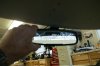
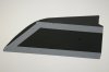
When you look out a rear view mirror mounted on the windshield of a GT40, you don’t see much. The rear bulkhead window is 5.5” tall. Over half of that is taken up with the rear spoiler. Another part of the remaining space could be filled with the filters for the eight-stack fuel injection. In other words, the rear view mirror is limiting to say the least. Those of you that are already driving probably know this; but I’m not driving yet.

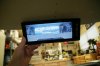
I wanted a rear view and backup camera with a good display. I searched high and wide to find a good solution. The first problem is the display. If it is a normal display, the aspect ratio is 4:3. If it is high definition it is 16:9. The problem with both of these is that when you get the display large enough to see (most are not), they are too tall to use as a replacement for a thin “mirror”. There are a few displays that use a 25:8 aspect ratio that looks more like a traditional mirror than a TV screen. Hence, it doesn’t intrude too far down in the field of view of the windscreen for a given width. I really only found one that was acceptable, the Tview RV808C. It has the 25:8 ratio but its screen is 8.8 inches wide with controls on the side making it an overall width of 10.6 inches. In my opinion, this is too wide but at least it is not correspondingly too tall (the mirror is 8” wide). There seems to be a huge push for OEMs to use rear view camera and displays that are of the proper aspect ratio and size, but we will have to wait until they become more available.

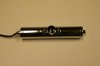
The second problem is the camera. Evidently most cameras are intended as a ‘backup” camera and hence have a wide field of view. I really want a “rear view” camera with a narrow field of view. I wanted a high definition color camera with a 90 degree FOV. Further I wanted one that could fit in a 1” diameter space. The best I could find was the BOYO VTL200C. It has a 130 degree FOV (too wide but much less than most) and reverses the image (to make it act like a mirror). That’s the good news. The bad news is that it is out of production. Not will willing to give up so easily, I called about 10 suppliers until I found one in stock. Sonic Electronix had over 40 in stock. I am not finished with the installation details yet, but I wanted to give this update in case someone wanted to buy this camera before they were totally unavailable.

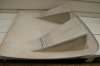
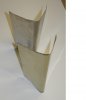
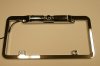
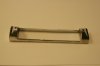
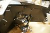
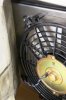
This BOYO is a license plate frame camera. The camera itself is mounted in a cylinder.

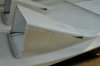
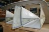
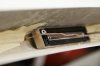
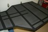
I modified the bracket that holds the camera to fit in the circular shape of the top of the rear window. This required tapering the bracket and removal of some of the sides of the bracket..

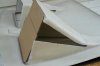
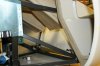
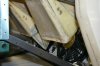
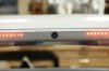
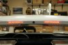
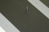
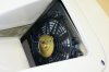
I drilled a 0.75” hole in the top of the rear clip and mounted the camera behind it.

As I said, I am not finished with the installation, but this shows what I am planning.

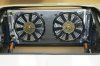
High-Level Brake Lights

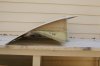
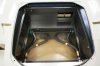
I wanted high-level brake lights so I mounted a LED strip in the rear clip just above the rear window next to the camera. I found the LED strip on Ali Express. Even with mounting these lights as high as physically possible, they are probably lower than regular brake lights on some cars and pickups…

I have a real glass rear window and I hope it does not cause any problems with the camera looking through it or the brake lights reflecting on it.

-Bob Woods
 

Attachments

  • Rear view mirror.jpg
    Rear view mirror.jpg
    101.8 KB · Views: 1,003
  • Tview display.jpg
    Tview display.jpg
    110.8 KB · Views: 1,019
  • license plate camera.jpg
    license plate camera.jpg
    72.6 KB · Views: 853
  • camera unit.jpg
    camera unit.jpg
    53 KB · Views: 690
  • modified camera mount.jpg
    modified camera mount.jpg
    50.4 KB · Views: 724
  • camera mounting.jpg
    camera mounting.jpg
    83.7 KB · Views: 898
  • backside of camera.jpg
    backside of camera.jpg
    89.9 KB · Views: 904
  • High level brake lights.jpg
    High level brake lights.jpg
    108.6 KB · Views: 922

Randy V

Moderator-Admin
Staff member
Admin
Lifetime Supporter
I love gadgets!! Trying to resist in my build but you and Bill Musarra are making some very good points to consider. I will be looking over my rear clip with consideration of something like this next weekend when I get back out to the shop..
 
Bob,
The unit you bought is a CMOS camera. The picture you will display may have a greenish tint to it and it will look a little fuzzy or slightly out of focus, even though it will give you a color picture. The VTL 420 on Ebay(quick search,other outlets may have it) is a CCD which gives a much sharper image and is a 130 FOV(field of view) camera for about the same price. I looked on Amazon and compared many other Boyo cameras, but a lot of them wouldn't give the FOV. Had to search elsewhere to find that. Sonic also has it for the same price.
The CMOS will work fairly well. It is what I have in mine only because they weren't making the ccds and if they did they were expensive. No one had narrow FOVs then either. I got lucky and found the 120s by swaping cameras around with the monitor I wanted. If you get a chance, visit an electronics store that has back up cameras and take a look at the CCD units compared to the CMOS. You may want to consider Tried to give a link to the Buyers guide on Amazon. Look up any of the BOYO cameras and find their "Need help deciding which back-up camera to buy? Check out our Back-Up Camera Buying Guide for information on back-up camera basics." It will include the link. When I copied and pasted it, it would lead to a dead link.

Bill
 
Last edited:
Bill,

Thanks, nice catch. I actually thought it was a CCD camera until I opened the box. My oversight. It looks like the camera tube might be the same, but the lens is more square. If so, it will probably fit in the housing that I already have, but I might have to enlarge the hole in the fiberglass. I will see if it will fit.

You're right, it isn't as clear as I thought it would be. I will probably get one. It didn't say that it could reverse the image, but I suspect it can.

-Bob Woods
 
Lizard Skin

Lizard Skin has two spray-on insulation products, one for sound insulation and one for thermal insulation. I used both. Some areas only need the thermal insulation (radiator tubes, central tunnel, panels in the front bulkhead area, and the inside center of the rear clip and front clip). Some areas only needed the sound insulation (front wheel well panels). Some areas needed both (rear bulkhead, and floor pan). They recommend to apply the sound control first and then the thermal insulation second. I applied 2 to 3 coats of each and probably should have used 3 to 4.

Since the Lizard Skin could crumble under load, I was careful to tape off all areas that would get rivets or screws so there would be no Lizard Skin between the panel and the frame. On the floor pan, I taped both sides so even the head of the rivet wouldn’t touch Lizard Skin.

After I applied the Lizard Skin, I painted all surfaces with a polyurethane paint to protect the coating. Several panels have Rivetnuts installed. I placed a cotton swab in each to protect the threads from the thick Lizard Skin and paint.

On the radiator tubes, I left a small section un-coated with Lizard Skin so we can see how effective the coating is. I had the occasion to re-solder a joint on the radiator tubes and I couldn’t hold my finger on the bare copper tube, but the thermal-coated section was just barely warm to the touch. Maybe this stuff works.

Panel Paint

I painted all of the aluminum panels and some of the fiberglass parts. I used the metallic charcoal grey to match the frame powder coat on surfaces that were next to the frame. I used a flat black in the front wheel well and the underside of the front and rear clips. I will let the professionals paint the body parts that show from the outside.

After doing all of the preparation, priming, and painting, I now understand why painters charge so much…

-Bob Woods
 

Attachments

  • Panel coated with Lizard Skin.jpg
    Panel coated with Lizard Skin.jpg
    57.3 KB · Views: 889
  • Floor pan.jpg
    Floor pan.jpg
    111.2 KB · Views: 1,059
  • Cotton swab in Rivetnut.jpg
    Cotton swab in Rivetnut.jpg
    119 KB · Views: 852
  • radiator bay.jpg
    radiator bay.jpg
    106.5 KB · Views: 1,099
  • Wheel well.jpg
    Wheel well.jpg
    107 KB · Views: 1,217
  • Paint and camera 014.jpg
    Paint and camera 014.jpg
    147.4 KB · Views: 1,318
Thanks for the comments.

I have started on the fan shroud for the radiator. As soon as I finish the fabrication, I will test it and several other aspects on the flow bench.

-Bob Woods
 

Attachments

  • radiator shroud 004.jpg
    radiator shroud 004.jpg
    86.5 KB · Views: 887
Looks like you plan to angle the fans downward just a bit. Not exactly perpendicular with the surface of the fins. Is there some flow reason for this or is it that you had to compromise the upper offset due to the nostrils maybe?

The Lizard skin does look good like others have said BTW.
 
Darrin,

I should have taken the photo at a different angle or not used the flash. The fans are angled up to help blow into the nostrils. The shroud spacing is 0.5" at the top and 2.5" at the bottom. This makes the shroud parallel to my splitter in the nostrils.

-Bob Woods
 
Radiator Fan Shroud

I have completed the fabrication of the shroud for the radiator fans. I used 0.5” gap at the top and 2.5” gap at the bottom. I made an offset to clear the hose fittings on the bottom and welded the sides on. I would have probably used a larger plenum, but I was constrained by the splitter on the nostrils. I clear it by 0.5”. I used Rivet Nuts to mount the fans. I may need to put stiffeners in the middle section to prevent any chance of vibrations.

The whole shroud is removable. I built brackets to attach the shroud at the normal mounting points for the radiator.

I might put flaps in the middle section as suggested by Phil in post #148; however, with everything I have done to improve cooling, I don’t think I will need it unless I plan to track the car at high speeds for a long time.

Next, I will retest the flow characteristics of this shroud on the flow bench (see my post #124). I will report the results as soon as I do the tests. I’m also going to test the effect of spacing between the engine radiator and the AC condenser to see if the condenser should be touching the radiator, should there be a gap, or a shroud.

-Bob Woods
 

Attachments

  • Shroud on radiator rotated.jpg
    Shroud on radiator rotated.jpg
    131.5 KB · Views: 876
  • Shroud installed.jpg
    Shroud installed.jpg
    182.7 KB · Views: 852
  • Nostril splitter rotated.jpg
    Nostril splitter rotated.jpg
    73.1 KB · Views: 745
  • Fan in nostril.jpg
    Fan in nostril.jpg
    104.8 KB · Views: 754
Back
Top