S2's Build Thread

Steve

Supporter
I just had my valve covers powder coated by them last week on Randy's recommendation. Reasonable price and top notch quality.
 

Scott

Lifetime Supporter
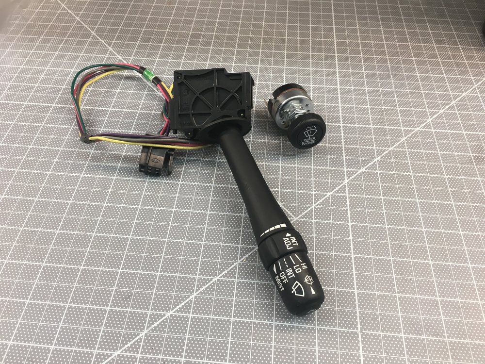
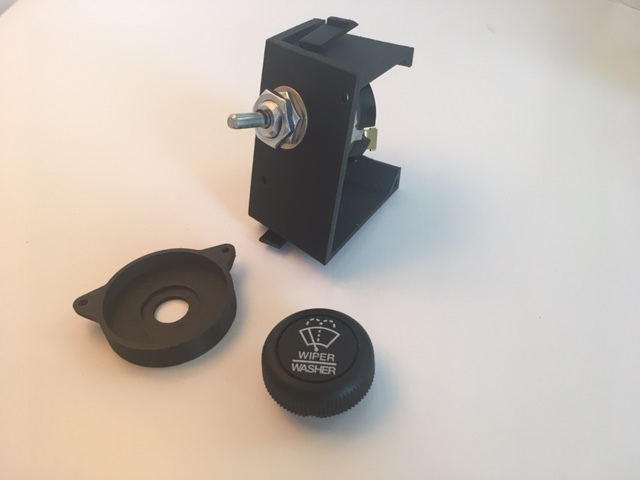
I dropped the dashboard in to see how room I'd have for the evaporator after I cut the hole in the foot box. The right stalk on the on the steering column projects in front of the middle binnacle where the controls and/or a tablet will go... yeah, that's about what you'd expect in a race-derived car. In addition, the stalk has a large number of windshield wiper settings and the wiper motor only has two speeds. My solution was to replace it with a smaller 80173 switch from Painless Performance.
IMG_1673.JPG


The stalk was very easy to remove once I figured out how it was done. There are two recessed tabs, one the top and one on the bottom. You simply depress the top one with a flat screw driver and the bottom one with your finger and pull. Separating it from the wiring harness was also easy; cut one wire tie and pop off one reusable wire clamp.

The next challenge was figuring out how to mount the switch. My first attempt was to 3D print two round pieces that sandwiched the switch around the steering column's upper and lower plastic covers. While it was easy to make the parts, it's a pain in the ass to install the switch and I will have the covers on and off a bunch of times during the build.

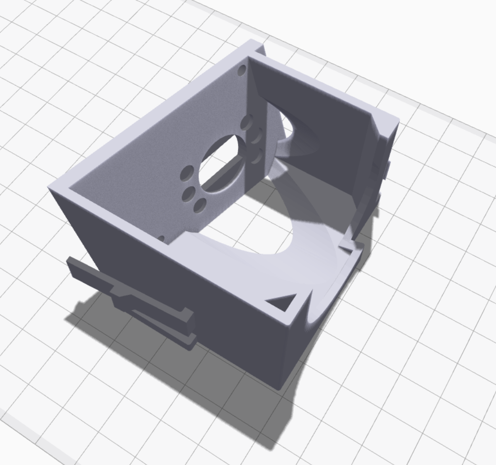
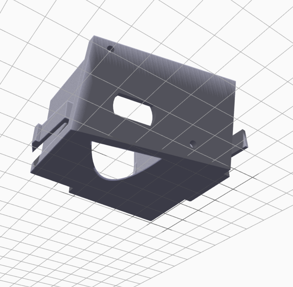
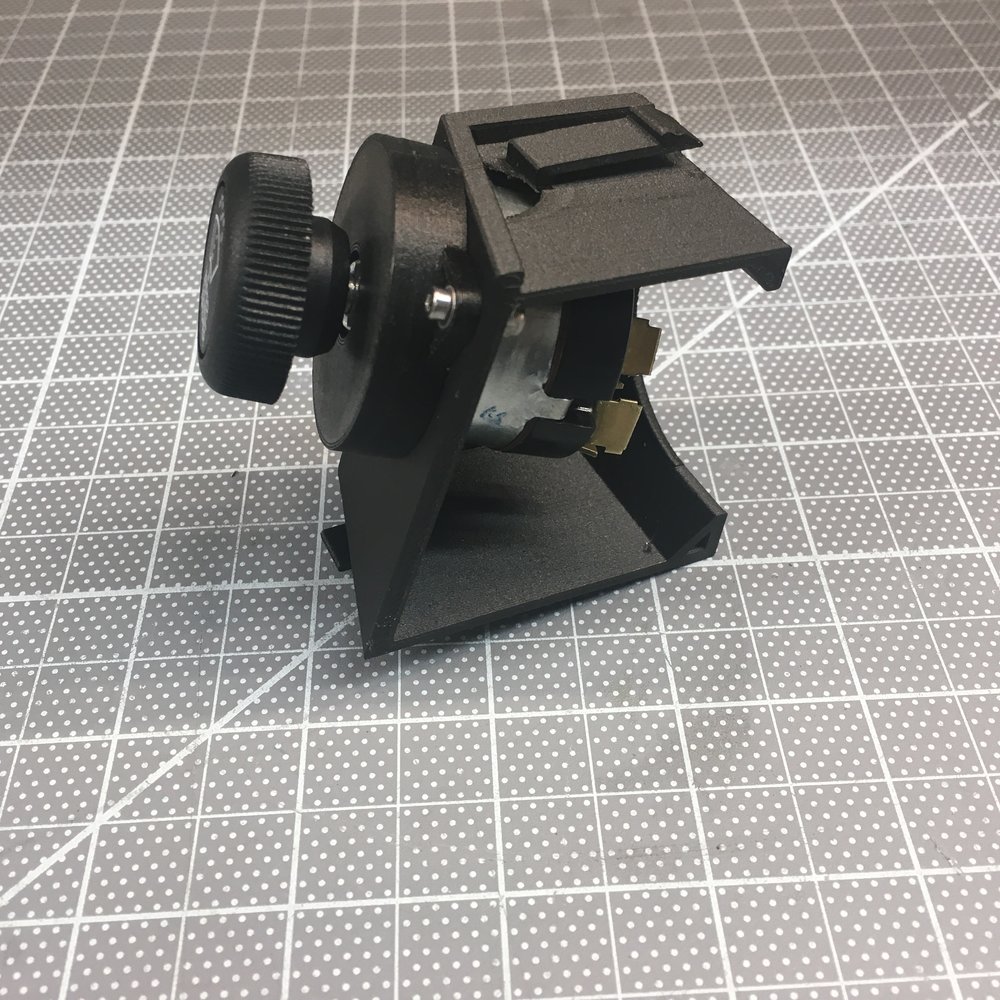
There's a reason the OEM version is mounted to the steering column, so that's what I decided to do. In the end it was a lot more difficult than I first thought - first time that's happened on this project LOL. The most challenging parts were the two clips (I'd like to thank GM for making them different shapes) and figuring out the exact position switch which requires a compound plane. I printed it in two pieces; the main box and a cover which completely hides the shaft and nuts.

wws_02.png


wws_01.png


wws_03.png


wws_04.png


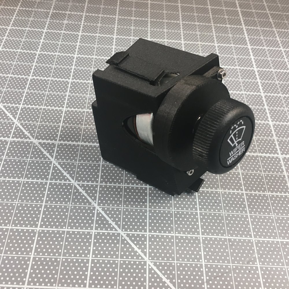
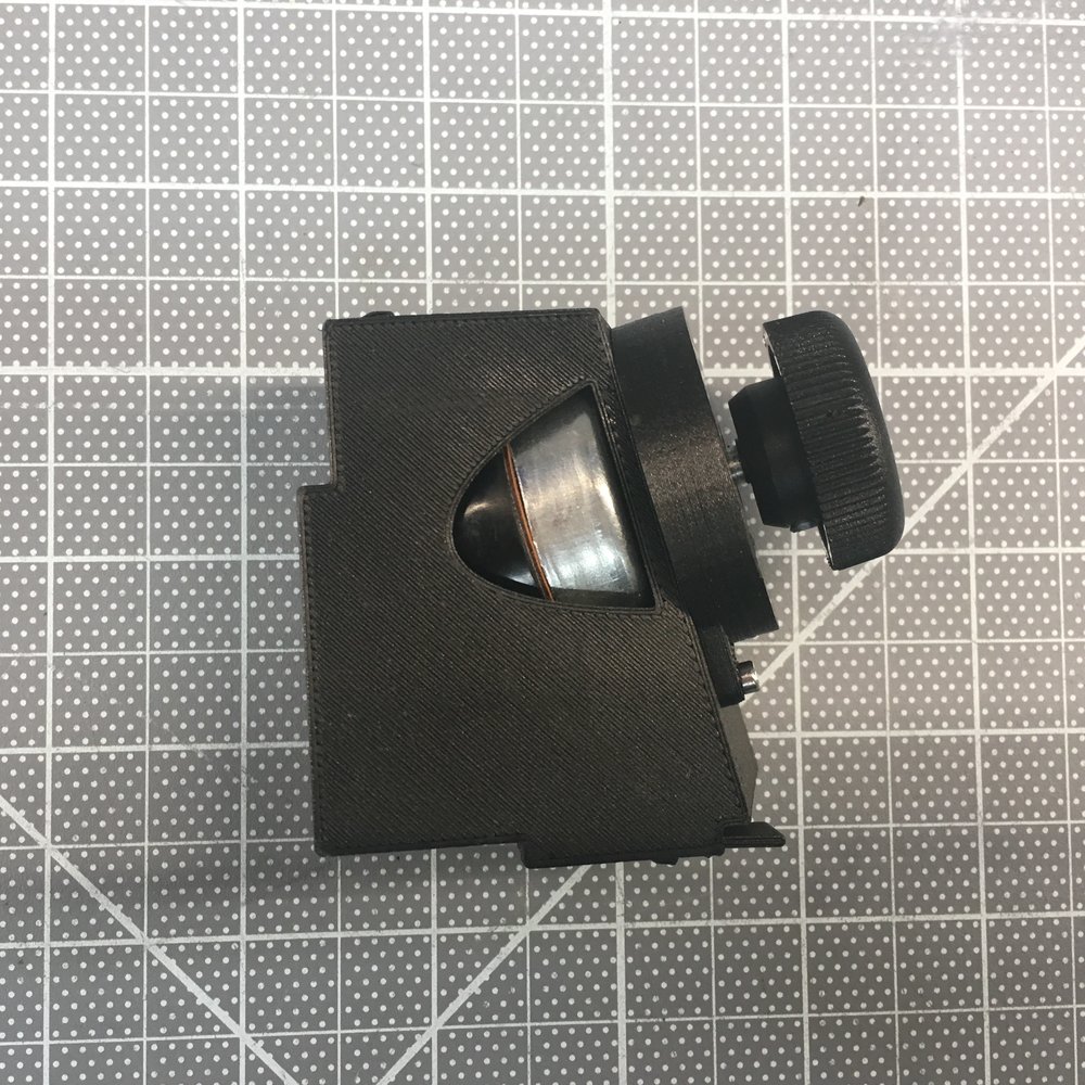
The following pictures show the assembled module. I thought about designing clips to hold the cover in place, but after the first two clips I am done with clips for a while and the screws and nylocs work just as well.
IMG_1711.JPG


IMG_1710.JPG


IMG_1712.JPG


IMG_1713.JPG


IMG_1754.JPG


As can be seen above, the switch protrudes through the side of 3D box. This requires a little material to be removed from the plastic receiver on the steering column. This is easily achieved with a sanding drum on a Dremel. The spade connectors also need to be cut shorter to fit. The plan is to solder a wire to them and crimp a connector on the other end. This is exactly what the OEM version does.

The following video shows how easy it is to install and remove the module. Listen carefully for the click... that has to be the most gratifying click in my entire life ;-)

I can't get video to embed, so here it is: IMG 1724 - YouTube


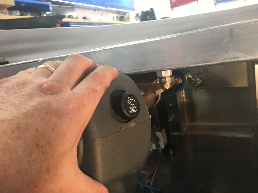
In the picture below I'm holding the top and bottom steering column covers in place. The switch doesn't look like it's centered in the hole, but that's just an optical illusion.

1498917512079
 
Last edited:

Scott

Lifetime Supporter
Mesa/Dan, thanks... it only took me a couple of tries to get it to this point LOL

Colin, I plan on making it available to other builders. I'll have to figure out how much... I'll price the same or lower than what it costs to send to one of the 3D print shops. I need to make a couple of tweaks... add a part/version number, add a strain relief for the wire, and a couple of other tweaks. If someone is interested in giving v1.0 a whirl PM me.

I spent hours trying to embed the video via the latest versions of IE and Chrome. IE generated an "URL not found" error. Perhaps that's because I'm on Windows 8.1. Chrome generated a security error. Pnut had same issue on Windows 10. In any event, I downloaded FireFox and it worked like a charm.

<iframe src="https://www.youtube.com/embed/TVCcSjoAznU" allowfullscreen="" width="560" height="315" frameborder="0"></iframe>
 

Scott

Lifetime Supporter
The switch is actually two switches; a three-position rotary switch (off, low, and high) for wiper speed and a momentary switch for fluid. The provided Infinitybox harness only supports one speed, but the wiper motor has two speeds. Since I'm going with a MoTeC PDM and a custom harness, I will have two speeds. In addition, I will use the fluid button to toggle an intermittent wiper function. Since the motor is self parking a one-second pulse with a configurable wait interval should provide OEM-like intermittent functionality. Holding the button down for more than one second will set the interval for the amount of time that the button is depressed.

I learned a lot, including a couple of basic tips when modeling things in 3D:

First, when you want to maintain a dimension make sure that you specify it from a point that doesn't change. For example, consider the simple box shown below. The first step is to draw and extrude the bottom. You draw the sides (likely using the offset command) and extrude the walls. Very simple. However, I typically draw on the top plane of the bottom piece because I'm extruding up -- seems intuitive to me. To do this, you simply subtract the height of the bottom from the desired height. However, if you later change the height of the bottom, you also change change the overall height. Sometimes, that's what you want, sometimes not. If you want to maintain the overall height, you draw on the bottom plane of the bottom piece and extrude to the desired total height. I found it a little counter intuitive to extrude the sides through the bottom piece, but it works just as well, no math is required and changing the height of the bottom has no effect on the overall height.

In the pictures below the bottom is 0.2" tall and the overall height is 0.7"


<NOSCRIPT></NOSCRIPT>
Extrude from top 0.5"


<NOSCRIPT></NOSCRIPT>
Extrude from bottom 0.7"


Second, I found that I had issues getting the edges defined by the intersection of planes at weird angles to look clean. The fix is to extrude one or more of the pieces well over the desired edge and then to simply extrude cut what's hanging over the edge. This is conceptually similar to how laminates or veneers are fitted in the real world. The pieces are cut larger than needed, glued into place and then trimmed with a router.
 

Scott

Lifetime Supporter
I just installed my dynamic split wing. At this point it's just bolted through the fiberglass, so I still need to build supports so that all forces are transmitted directly to the rear suspension cross brace. When the ECU first powers up it cycles through its four modes: low-speed cornering, high-speed cornering, straight, and braking. You can tune the angle of attack for each mode and save up to 10 different tunes for different conditions or tracks. The ECU uses VSS from the CAN Bus and its built in accelerometers to determine what mode to put the wing in when driving.


<iframe src="https://www.youtube.com/embed/XDB7iaufwao" allowfullscreen="" width="560" height="315" frameborder="0"></iframe>

Active Wing video
 
Last edited:
That active wing looks trick Scott.

How much downforce do you need to design in to your brace? Is it more than a normal wing since this one can do air braking?
 

Scott

Lifetime Supporter
Mason,

I haven't sorted it out yet. All of the actuators and motor controllers are in the power pods which also act as heat sinks. So nothing other than the ECU goes inside the car which makes for a very clean install on a mid-engine car. Each pod requires three holes, two for the mounting studs and one for the connection to the ECU. They provide a thin carbon fiber back plate to mount to the backside of the fiberglass.

I will beef this up with a 1/2" thick aluminum circle bonded into the tail. I will then weld two threaded steel fixtures to the top of the rear suspension cross brace. A support post with a welded "hat"(i.e. 3/16" steel circle) will be threaded into the fixture. Rotating the post/hat gives me fine grained height adjustment. A jam nut keeps it all in place. Basically just like most of the suspension. So it will be as strong as whatever a 1/2" Grade 8 bolt threaded into steel can handle in compression... something else is going to give before that ;-)

I'll draw it up when I get a chance.
 
I look forward to seeing it built, that definitely sounds like a stout wing support! I've always been intrigued by the active aero/braking setups on the Porsche turbos and McLaren P1 etc... I would love to have one that can be lowered into the body, but had no look finding the actuators from an aftermarket company.

This looks like the next best thing, I'd love to see active/inactive track numbers once you hit the road!
 

Scott

Lifetime Supporter
Here's a close up of the wing's ECU and a wired remote that enables the angle of attack for each mode to be adjusted while driving.
1500325053562
 

Michael Fling

Supporter
I just installed my dynamic split wing. At this point it's just bolted through the fiberglass, so I still need to build supports so that all forces are transmitted directly to the rear suspension cross brace. When the ECU first powers up it cycles through its four modes: low-speed cornering, high-speed cornering, straight, and braking. You can tune the angle of attack for each mode and save up to 10 different tunes for different conditions or tracks. The ECU uses VSS from the CAN Bus and its built in accelerometers to determine what mode to put the wing in when driving.


<iframe src="https://www.youtube.com/embed/XDB7iaufwao" allowfullscreen="" width="560" height="315" frameborder="0"></iframe>

Active Wing video

Really nice Scott!
 

Randy V

Moderator-Admin
Staff member
Admin
Lifetime Supporter
Jim Hall called and wants to know when you'll have it at the track!
---
Be really careful with that... From my experience movement of the wing should be balanced with an adjustment to the splitter...
 

Scott

Lifetime Supporter
Jim Hall called and wants to know when you'll have it at the track!
Randy, Jim Hall will have to wait a while for the car to be on the track, but he's free to drop by any time and check the car out LOL

I did a fair amount of research on active wings and his Chaparral 2C was the first. It was designed to lie flat for low drag on the straights and to flip up under braking. The car's clutchless semi-automatic transmission freed up the driver's left foot to operate the wing mechanism.
chaparral_2c_wing2.jpg


chaparral_2c_wing1.jpg


The Chaparral 2E swapped the integrated wing for one mounted on tall struts. They sure got clean air up there, but I wonder how many bird strikes they had. In addition to activating the wing, the pedal also opened and closed the nose ducts.

1495980021153


The active split wing was pioneered by Nissian's R381which won the 1968 Japanese Grand Prix. The left and right wing were independently driven by hydraulics that moved the wings up or down in order to increase cornering ability by providing more down force on the inside wheel.
1495973786962
 

Randy V

Moderator-Admin
Staff member
Admin
Lifetime Supporter
Just be aware that if you dial in too much rear wing whilst in a high speed corner, you may go for a ride like I did in my Cobra about 10 years ago.... Sudden high-speed understeer is a good way to ____________!
 

Scott

Lifetime Supporter
The left stalk on the steering column gets in the way when popping the dashboard in and out. I'd like to temporarily remove it. The right one is easy to pop in and out. Any know how to pop the left one out?
 

PeteB

GT40s Supporter
If you have the Cadillac column, there's one or two screws holding it in. I can't take the dashboard out without removing both stalks.
 

Scott

Lifetime Supporter
Because I went with a Daily Engineering dry sump I need to relocate the A/C compressor to the driver's side of the car. This requires a custom A/C compressor bracket and potentially a custom alternator bracket. The engine is currently installed which makes it really difficult to take measurements. Does anyone know where I can get the bolt pattern for the 8 bolts circled in red in the picture below? They're OEM LS7 block and heads. I'm also looking for the distance of the pulleys from the face of the block.
 

Attachments

  • BoltPattern.jpg
    BoltPattern.jpg
    275.8 KB · Views: 350
Back
Top