S2's Build Thread

Ken Roberts

Supporter
Here is a high mounted "tight" alternator bracket that might work. It is on the Corvette belt wrap. Then you would need to find or design a low mounted compressor bracket. Trying to find the correct length belt that will serve all the pulleys and in the correct "thicker" width will be the real challenge.

It is near the bottom of the page. K10182

LS1 LSx Compact and Street Rod brackets
 
Measuring the belt length is the easy part, whether anyone makes that belt in the length you need might be the harder part.

While we are talking blower motors or any 'high-at-the-front' intake manifolds for that matter. I am noticing that my lower passenger mount AC position may be a problem. The 'final' engine installation was done with the body off the car, unfortunately there was recent cause to remove the engine. When doing so, the top of the blower hit the bottom of the tail of the roof scoop before the AC pump cleared the passenger side chassis engine standoff. This necessitated the removal of the AC pump before the engine could be extracted.

All this may be a moot point for the later cars with the bolt in engine mount cross member, but for the rest of us, something to think about :(
 
Last edited:

Scott

Lifetime Supporter
Ken, thanks for the pointer. I don't want to mount the alternator that high on the driver's side because that's where I plan to put the coolant expansion tank (the passenger's side is full with throttle body and intake). I plan on mounting the alternator close to the block and the compressor where the power steering pump is often placed (see picture).

While the brackets might be a challenge, I don't think I'll have a problem finding the right length belt. I have an 8-rib set up and if you look at the Gates catalog they offer a bunch of shorter and 35 longer 8-rib belts with the longest being ~43" longer. If I had an 11 rib setup like the LS9, I'd have a big problem because they only offer a few lengths!

Another challenge is that the compressor has a 6-rib pulley which presents a challenge because the pulley is integrated with the clutch. CV Racing offers this aftermarket 8 rib upgrade for $97.50, but it's a pain in the ass to install:

Please note that removal / installation of the compressor clutch is an involved process and it may void the original warranty on your compressor. At a minimum you will need an impact wrench, hydraulic press, snap ring pliers, shim stock and feeler guages to set the proper clutch gap. We generally recommend purchasing a complete compressor but this is an option for those customers with above average mechanical abilities.

Another option would be to go with a SD 709 compressor which comes with an 8-rib pulley. However it has a 6k RPM limit as opposed the 9K limit with the one supplied in the kit. With a pulley ratio of 1.7 that would mean that the RPM window switch would cut the compressor off at 1,364 RPM which seems really low! If anyone has done the above upgrade or has other thoughts, let me know.

Mesa, I spoke with my engine builder and he mentioned that I could mount a 6 rib pulley on the damper and run the compressor and the alternator on it. That way I can keep my current belt and I could run a smaller diameter pulley to optimize the ratio for compressor speed. To your, point that might make it more challenging to get the engine in and out.
 

Attachments

  • Plan.jpg
    Plan.jpg
    240.6 KB · Views: 425
Last edited:

Scott

Lifetime Supporter
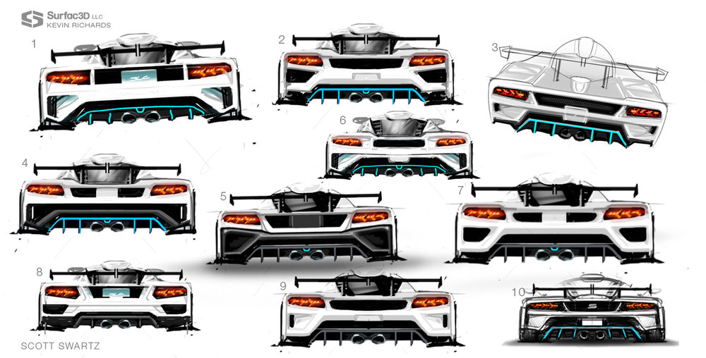
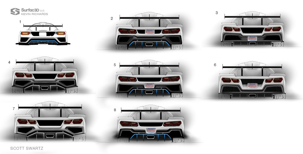
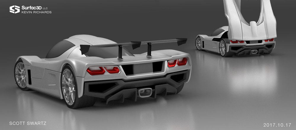
I plan on replacing the rear 12" or so of the street tail with a custom piece. I retained Kevin Richards from Surfac3D to create the sketches and 3D models. The key design elements are:

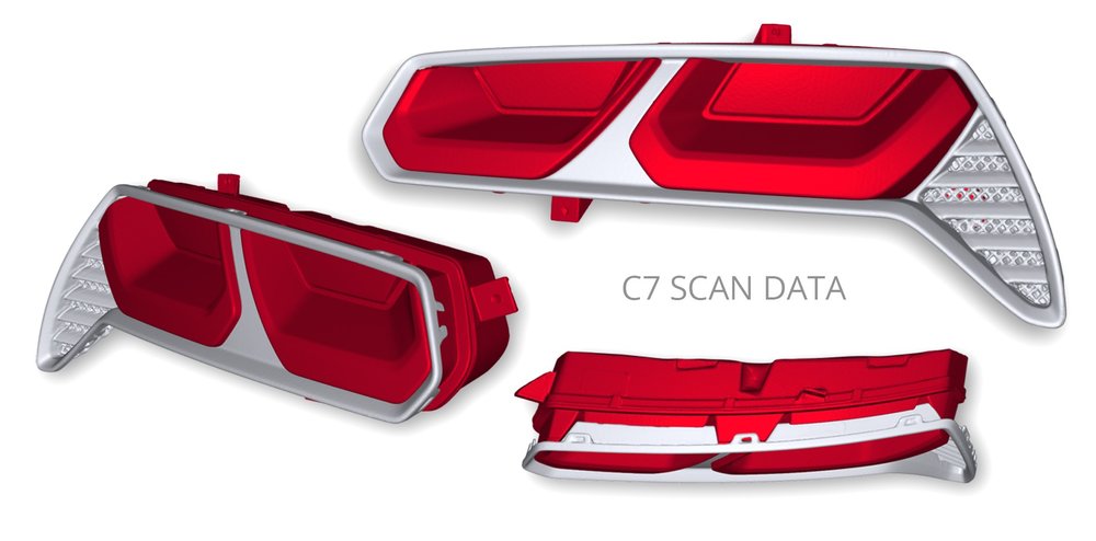
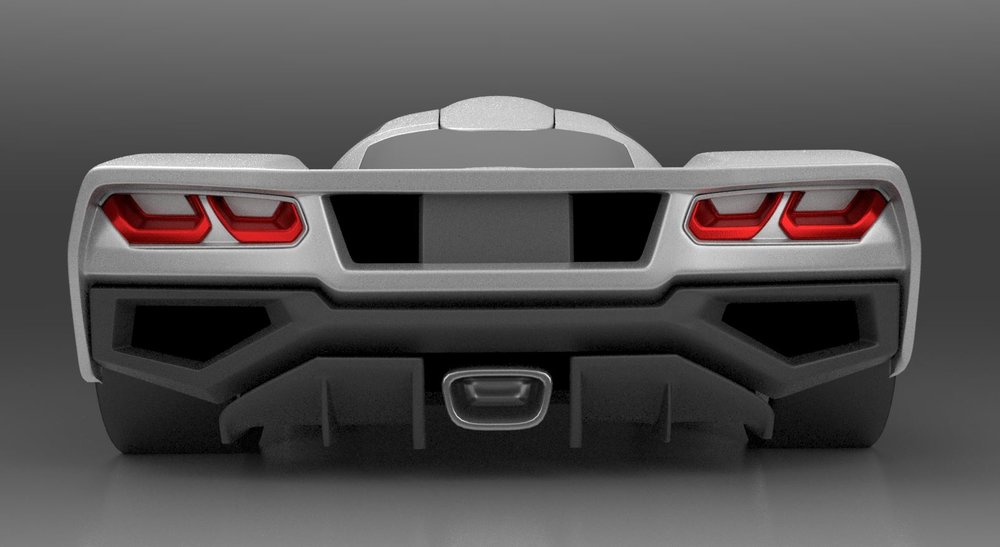
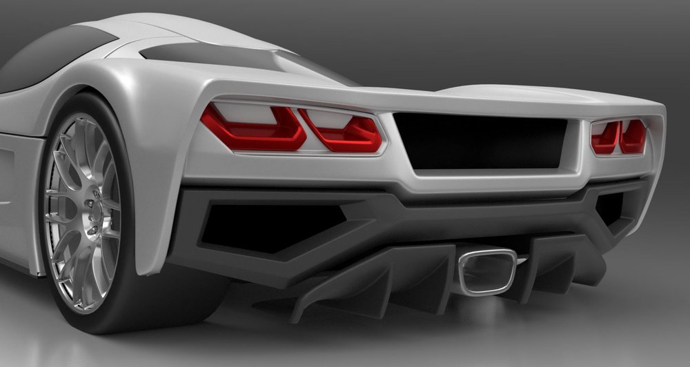
Unique taillights: While the tail lights provided in the kit are OEM, I think the car deserves something better. I don't want anything round.

More vents: The engine compartment gets hot and more vents are functional, plus they look cool.

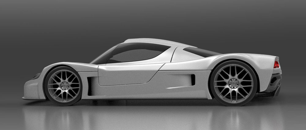
Remove duck tail: A dynamic wing will be mounted above the tail section. The duck tail conflicts with a wing both aesthetically and functionally.

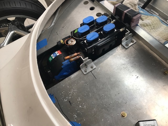
Fixed diffuser: The diffuser is molded into tail and it provides the mounting points for the hinge. This means that you need to elongate the holes for the exhaust tips to clear. While removable bezels can cover the holes, they are a pain in the ass. If the diffuser is fixed and the exhaust passes through it, there is no need for elongated exit holes or bezels. In addition, the current molded-in diffuser doesn’t appear all that functional when compared to the race tail. Lastly, the diffuser can project out the rear further which will provide more room for the exhaust (the current diffuser clears the ground by less than a quarter of an inch when the tail is in the vertical position).

Exhaust: The exhaust should exit through the diffuser, ideally with a crossover and a single Lambo-like exhaust tip. I like the external appearance and sound of Peter's exhaust, but I'm thinking of mounting the mufflers low and parallel to the ground. I have a Ricardo which is huge so I'll have to see what's possible.

Hinging: A fixed diffuser requires a custom hinge that mounts to the top of the suspension cross brace. Given that the diffuser is fixed the pivoting piece of the tail will be much lighter.

Tire: The tires are hardly visible at all from the rear and I'd like to see a little rubber. Something midway between the street and race tails.
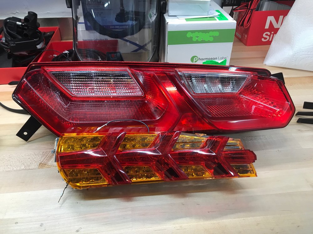
LAMBO LIGHTS
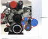
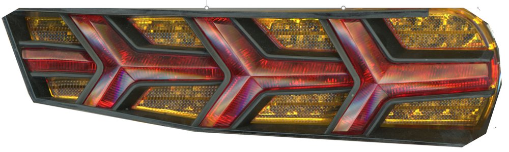
My first attempt was to modify some aftermarket Lambo-like sequential lights from Buddy Club as shown in 
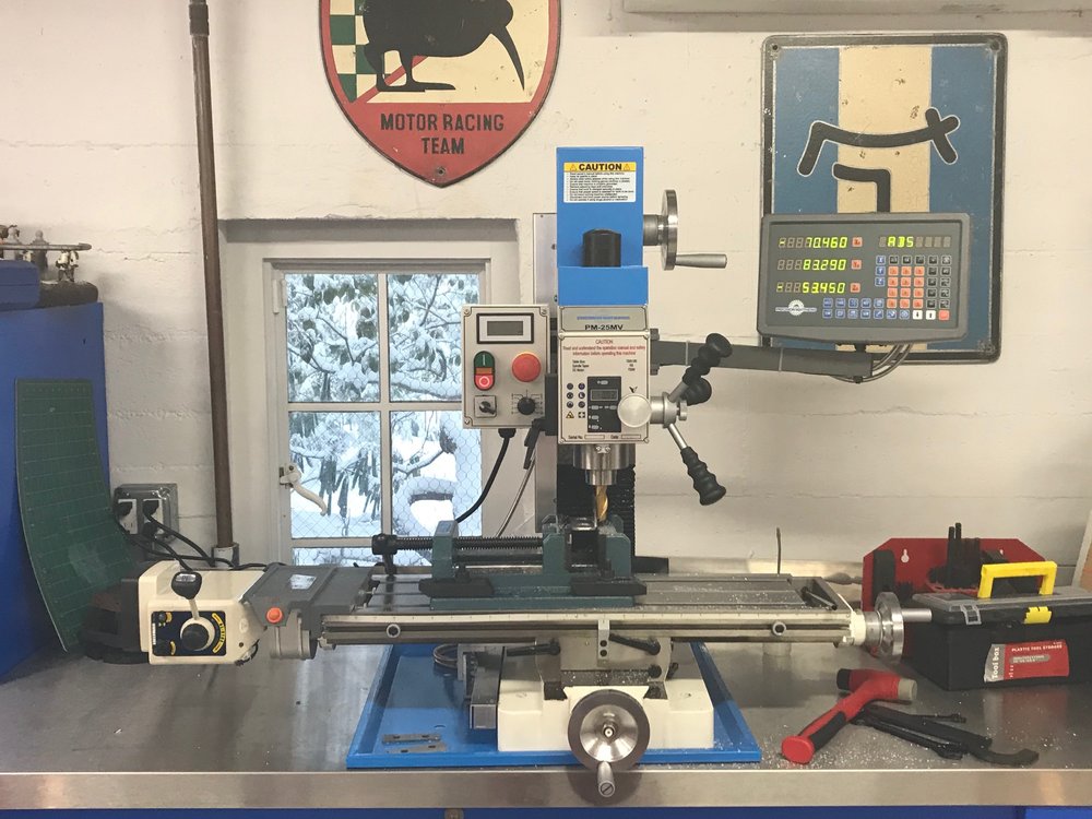
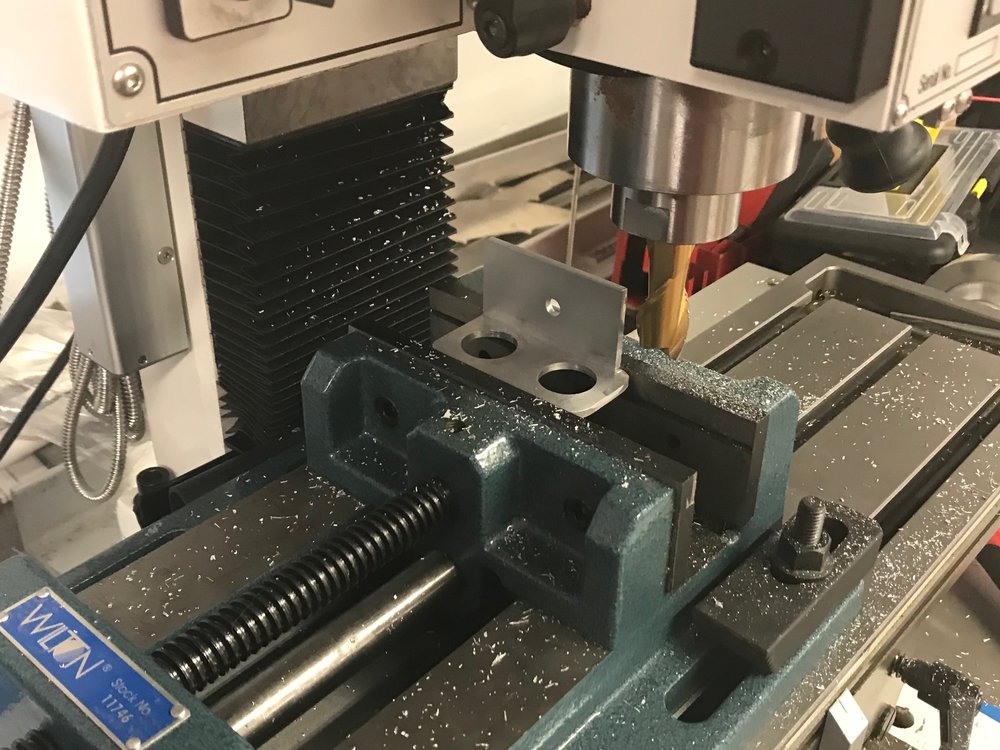
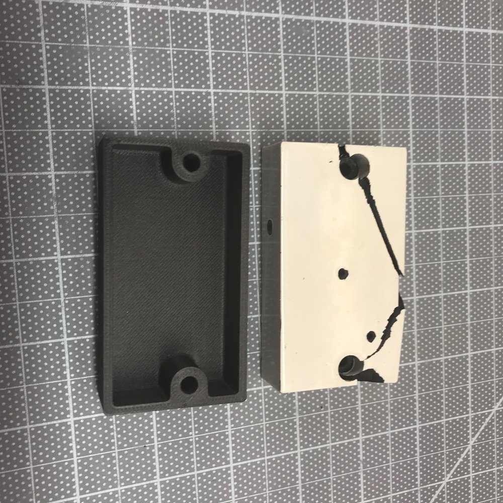
this video. I spent a bunch of time cutting them out of the huge casing, designing a 3D printed bezel and making a mold to vacuform a clear lens.

brakelight_1.jpg

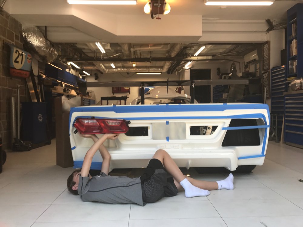
Kevin did some sketches which looked great, but when he saw the light in person he mentioned that the LEDs were pointed in a weird direction, so we powered it up and they were clearly designed to project light 20 degrees different that how they'd be mounted on the SL-C. While they'd look great, I decided that it was dangerous to have the brake lights set up sub optimally. Too bad, as they would have provided me with a completely unique look.
Surfac3d-Swartz-SLC-Ideation+1.0.jpg
 

Scott

Lifetime Supporter
Ken, I was just about to post my attempt two, let's hope I don't need three LOL...

So I spent a lot of time looking for another set of DOT approved tail lights. The challenge was finding something that wasn't round and was flat enough to work with the SL-C... you'll note that most modern tail lights wrap around the side of the car. In the end, I decided to go with C7 lights with the "fang" in the bezel cut off. Kevin did the following sketches 2-8 bases on C7 lights:
Surfac3d-Swartz-SLC-Ideation3.jpg


I liked the look so I bought a pair. They're a hell of a lot bigger than the Lambo lights (see pic below) so I had my son hold them up to see what they'd look like. In the picture below the bottom of the horizontal blue tape is where the top of the tail will be when the duck tail is removed.
IMG_2478.JPG


IMG_2476.JPG


The picture below is a cut-and-paste image of the C7 lights in a cleaned up version of the 3D scan that Mason posted. Note that body split line in the spyder was carried over to the tail section resulting in the splitter and tail lights remaining fixed.
SSLC-RearDeckOpenOnly.jpg


I have since had the C7 light and bezel scanned and the next step is to incorporate those scans into the 3D model.
C7+Tail+Light+Scan.jpg
 
Last edited:

Randy V

Moderator-Admin
Staff member
Admin
Lifetime Supporter
I like the C7 lights in there...
First SLC Street Tail that I think compliments the rest of the car’s race-ready looks!
 
Scott

The idea on how to redesign the rear bonnet is a stroke of genius. It has my brain going wild........

Your approach is first rate! :thumbsup::thumbsup:
 

Scott

Lifetime Supporter
Thanks guys. Big difference between a mesh model and reality, but the tail is moving along.

I spent a fair amount of time looking for a CS-130 style alternator and I found Mechman Alternators. They custom make alternators with really impressive low RPM output as demonstrated in this video:

[ame]http://www.youtube.com/watch?v=p-j3QNVXN6k[/ame]
MECHMAN BILLET 150AMP STREET ROD ALTERNATOR VS MSD - YouTube

Mechman's Elite & S Series have the following advantages:

  • Six-phase hairpin stators: provide incredible efficiency resulting in extremely high output at low engine RPM, less energy wasted in the form of heat, and more horsepower to the wheels.
  • Precision balanced low-mass rotors: allows shaft speeds of 20,000+ RPM.
  • High Pole Count: results in less electromagnetic interference with electronics.
  • Twin internal rectifier plates: most other high-performance alternators have only one rectifier with six diodes, theirs boast 12 press fit-diodes with 300% more surface area to dissipate heat. This results in cleaner power and better durability.
  • Twin high efficiency cooling fans: excellent airflow.
Perhaps most surprising to me is that these are one-wire and still have great power generation at low RPMs.

I went with a B8165170M with a 54 mm pulley. It has a billet aluminum case and rated at 170 amps. However, what's really impressive is that it will generate 120 to 130 amps even at my low RPM idle! I just got it today, and it's beautiful. I went with the "machined" finish because that's in keeping with all of the CNC'd suspension parts.
IMG_3149.jpg


IMG_3150.jpg
 
Last edited:

Scott

Lifetime Supporter
The 3D scans of the tail light and the bezel have been incorporated into the model. Kevin had to temporarily remove some of the refinements on the prior model to make the change, but this is now a lot closer to reality. You will note in the profile shot that the tail bows out in the middle. That's because the lights have a slight curve to them. More space back there is a good thing and I think that the SL-C's street tail is a little too flat for a street car. In fact, I might stretch the tail more depending on how the exhaust mocking goes. Thoughts?
20171219-c7ScanCleanup-RearView.JPG

20171219-c7ScanCleanup-rearquater.JPG


20171219-c7ScanCleanup-Side.JPG
 
Looks really refined and designed. Not a fan of the Corvette tail lights, but they look pretty good in this iteration.
Looks like the nose has been shortened slightly or is it just the angle?
 
Ken, I was just about to post my attempt two, let's hope I don't need three LOL...

So I spent a lot of time looking for another set of DOT approved tail lights. The challenge was finding something that wasn't round and was flat enough to work with the SL-C... you'll note that most modern tail lights wrap around the side of the car. In the end, I decided to go with C7 lights with the "fang" in the bezel cut off. Kevin did the following sketches 2-8 bases on C7 lights:
Surfac3d-Swartz-SLC-Ideation3.jpg


I liked the look so I bought a pair. They're a hell of a lot bigger than the Lambo lights (see pic below) so I had my son hold them up to see what they'd look like. In the picture below the bottom of the horizontal blue tape is where the top of the tail will be when the duck tail is removed.
IMG_2478.JPG


IMG_2476.JPG


The picture below is a cut-and-paste image of the C7 lights in a cleaned up version of the 3D scan that Mason posted. Note that body split line in the spyder was carried over to the tail section resulting in the splitter and tail lights remaining fixed.
SSLC-RearDeckOpenOnly.jpg


I have since had the C7 light and bezel scanned and the next step is to incorporate those scans into the 3D model.
C7+Tail+Light+Scan.jpg

Excellent work! Where did you get the lights scanned?

JP
 

Scott

Lifetime Supporter
Excellent work! Where did you get the lights scanned?

JP

JP, Kevin brought the tail light to the company that he usually uses and they quoted $2k which he agreed seemed out of wack. I found a local place outside Boston, 3D Printsmith. Sean was great to work with and I recommend him highly. He charges $450 per part which includes the following:

  • The 3D scanning unit will be setup on a tripod and calibrated (at a pre-determined focal distance from the object).
  • The structured light 3D consists of one white light projector and one or two digital cameras. Several scans of the object will be taken from different views to captures as much geometry as possible. A “scan” view is the process of the projector projecting white line patterns onto the object while the camera records the projected line patterns on the object in order to reconstruct the viewed scene in 3D.
  • A very thin (~0.001”) spray coating will be applied to the surface of the objects to provide a uniformly bright, matte surface for the scanner. This costing is water soluble, rinses or wipes away with water, and will no harm the object’s surface.
  • Each object scan set will be post processed to form a “watertight” STL mesh file. The method of post processing involves aligning and registration of all scan views taken of the object, then merging into a single file, finally cleaning the data of any anomalies.
 

Scott

Lifetime Supporter
I have been taking flying lessons in a Cessna and over the holiday I got to fly my Dad's Pilatus PC-7 with an instructor. It's a high-performance turboprop used as a military jet trainer in many countries including the USA and for close air support by other countries. I believe this one came from the Angolan air force complete with hard mount points on the wing an non-functional triggers on the joy stick. If the Cessna is a scooter this is a 1,000 HP SL-C. Even at idle it taxis so fast that you need to keep on the brakes. On takeoff the engine generates so much p-factor you pretty much have to keep the right pedal to the floor. It's rate of climb is 2,150 ft/min so the throttle has a built in electric rudder trim so that you don't get fatigued holding right rudder in during climbs.
IMG_3187.jpg


IMG_3192.jpg


IMG_3191.jpg


IMG_3194.jpg

I got to do the majority of the flying so I was not able to take a lot of pictures. I didn't expect the scenery to make such a big difference, but WOW is it a lot more fun than flying back east. The tandem seating and bubble canopy provides a very different flying experience, especially when you're upside down... yeah, the instructor had the stick during those maneuvers. I loved the military stick vs. yoke (aka control wheel) in the Cessna. It was so precise and intuitive. For example, the pitch trim is a thumb button the top of the stick. You just need to stay on top of things because everything happens much faster than in a Cessna and without realizing it you can be climbing or descending over 1,000 ft/min.

I got to fly through some canyons which was a total blast, especially since the instructor was sitting in front ensuring that I didn't get into trouble. I wish I had some pictures of those runs, but no way in hell was I going to even think about trying to take a picture. Canyon flying is particularly dangerous with a naturally aspirated engine because at these altitudes performance is sluggish and if you fly into a box canyon you won't be able to climb out. The PC-7 will climb all of the way to 33,000 ft so long as you have oxygen to keep you from passing out.
IMG_3196.jpg


IMG_3204.jpg


Last edited:

Brian Kissel

Staff member
Admin
Lifetime Supporter
That's simply awesome. Sounds like a blast, that I could never experience, too many heart issues. Congrats !!!!
 
JP, Kevin brought the tail light to the company that he usually uses and they quoted $2k which he agreed seemed out of wack. I found a local place outside Boston. Sean was great to work with and I recommend him highly. He charges $450 per part which includes the following:

  • The 3D scanning unit will be setup on a tripod and calibrated (at a pre-determined focal distance from the object).
  • The structured light 3D consists of one white light projector and one or two digital cameras. Several scans of the object will be taken from different views to captures as much geometry as possible. A “scan” view is the process of the projector projecting white line patterns onto the object while the camera records the projected line patterns on the object in order to reconstruct the viewed scene in 3D.
  • A very thin (~0.001”) spray coating will be applied to the surface of the objects to provide a uniformly bright, matte surface for the scanner. This costing is water soluble, rinses or wipes away with water, and will no harm the object’s surface.
  • Each object scan set will be post processed to form a “watertight” STL mesh file. The method of post processing involves aligning and registration of all scan views taken of the object, then merging into a single file, finally cleaning the data of any anomalies.

Nice. Thanks for the info!
 

Scott

Lifetime Supporter
I finally got around to installing the Restomod Air evaporator. I just needed to man up to cut a big hole in the monocoque. Allan recommended that I use Bosch T227D jig saw blades. Eight teeth per inch (TPI) seems way to few for metal, but it's my understanding that the higher TPI blades easily become clogged. I used some cutting fluid and they cut like butter... well, maybe frozen butter.
IMG_2512.JPG


I got the Restomod Vapir III to fit, but it was going to a nightmare to get the hoses routed, so I went with a Restomod Bantam. According to Restomod Air even the smaller Bantam has more cooling and heating capacity than the largest Gen IV unit from Vintage Air. I'm not sure about that, but I think that it will certainly be better than the supplied Vintage Air Slimline.

I made some brackets out of right angle aluminum and mounted the unit (I'm not going to trim the brackets until I figure out the exact height of the dashboard). The net result is that the Bantam takes about as much vertical space as the Vintage Air does when it's mounted under the the foot box (i.e., no hole). That said, the Bantam extends further towards the front which leaves less room for your toes to point up.
IMG_3164.jpg


I also got my Precision Mathews PM-25MV milling machine setup today. IMO it's the best entry-level, bench-top, Chinese mill. It has a variable, brushless 1 HP motor, a three axis DRO and an x-axis power feed. It should handle my needs. I managed to crack the chip shield bracket the first time that I used it. According to the manufacturer, 99.9% of the users remove it so I just 3D printed a replacement bracket to hold the switch and I tossed the rest in the trash.
IMG_3220.jpg

IMG_3221.jpg
IMG_3219.jpg
 
Nice AC, how far above the footbox are the duct manifolds? Do you have a picture from the bottom (foot room intrusion)?

Good thing I don't live closer, we would be bartering skill sets all day long.
 

Scott

Lifetime Supporter
Mesa,

I'm happy to barter anytime, but do two slow builders who like to invent things to do make things go faster or slower LoL

IMG_3223.jpg


The bottom of the evaporater isn't flat. There is 12.5" vertical space between the bottom of the evaporator and the floor at the horizontal cross bar (i.e., directly in front of the passenger). That reduces down to 10" as you move forward. I think Allan measured one of his recent cars to have 10" of clearance. However, the Vintage Air unit doesn't extend nearly as far into the foot box so you have more toe room once you're seated.

IMG_3224.jpg


The foot box slopes forward at about 7 degrees so the height of hoses from the foot box varies. The bottom of the right angle in the picture below is where I expect the bottom of the dashboard to be.The evaporator projects 3.25" above the foot box at the cross bar and about 5" at the point where it ends in the foot box. The plan is to have the 3D printed manifold directly under the dashboard. The hoses will attach to the manifold directly under the dash board but they will quickly slope down to the top of the foot box for mounting.
 
Back
Top