Stephan's SLC Build Log

Stephan E.

Supporter
...and back at it...

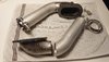
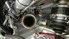
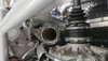
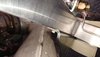
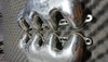
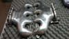
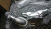
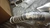
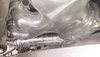
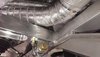
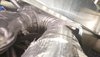
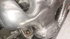
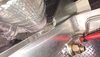
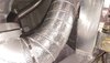
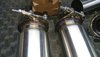
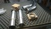
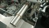
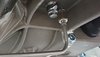
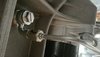
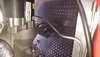
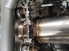
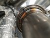
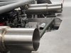
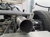
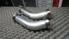
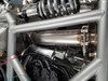
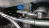
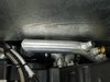
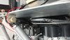
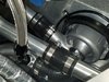
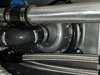
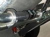
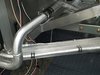
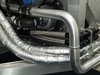
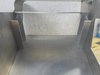
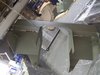
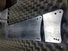
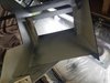
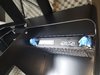
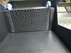
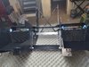
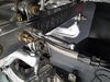
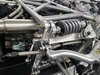
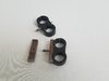
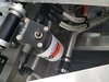
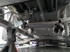
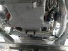
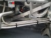
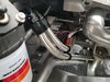
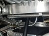
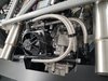
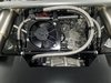
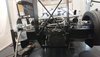
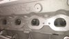
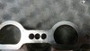
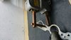
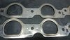
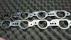
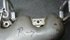
At some point during my travels I started to think about how loud the initially planned side exhaust would be with an engine pushing out that much HP at that RPM level. For the sake of my hearing I tossed the entire idea, decided on a rear exhaust solution which involved the relocation of the engine management electronics which will be covered in a separate post. Here are my first attempts to make an exhaust fit where the word "tight" entered a new dimension. In addition, Mercury Racing left me a little present with their home made exhaust manifold bolt pattern. Since there are no matching gaskets on the market I had to made them too. This series of pictures starts with the modifications to the manifold and gaskets...
 

Attachments

  • DSC_0151.JPG
    DSC_0151.JPG
    303.4 KB · Views: 503
  • DSC_0111.JPG
    DSC_0111.JPG
    557 KB · Views: 489
  • DSC_0120.JPG
    DSC_0120.JPG
    290.8 KB · Views: 440
  • DSC_0124.JPG
    DSC_0124.JPG
    380.7 KB · Views: 353
  • DSC_0125.JPG
    DSC_0125.JPG
    674.8 KB · Views: 433
  • DSC_0115.JPG
    DSC_0115.JPG
    273.6 KB · Views: 458
Last edited:

Stephan E.

Supporter
Here is a series of pictures of the tacked exhaust collectors and first test fitment. This engine is a few inches wider than a LS series and the manifolds sitting over the frame rails. I maxed out at about 10 degree tilt due to spacing issues with the collector flange bolts.
 

Attachments

  • DSC_0101.JPG
    DSC_0101.JPG
    401.1 KB · Views: 437
  • DSC_0126.JPG
    DSC_0126.JPG
    369 KB · Views: 459
  • DSC_0080.JPG
    DSC_0080.JPG
    264.8 KB · Views: 405
  • DSC_0097.JPG
    DSC_0097.JPG
    221.5 KB · Views: 395

Stephan E.

Supporter
Preparing for ceramic coating. Here you can see how I am removing the weld splatter and hand buff with fine Scotchbrite before throwing the manifolds into a ceramic ball media vibrator bowl. The coated manifolds in Chrome effect and the collectors in matte finish since there are being wrapped too to minimize heat radiaton. I had to find a new routing for the shifter cables due to heat exposure. The cylinder heads are too wide to allow for the traditional routing.
 

Attachments

  • DSC_0117.JPG
    DSC_0117.JPG
    414.7 KB · Views: 413
  • DSC_0118.JPG
    DSC_0118.JPG
    518.2 KB · Views: 475
  • DSC_0147.JPG
    DSC_0147.JPG
    533.6 KB · Views: 450
  • DSC_0148.JPG
    DSC_0148.JPG
    429.4 KB · Views: 422
  • DSC_0153.JPG
    DSC_0153.JPG
    252.8 KB · Views: 446
  • DSC_0154.JPG
    DSC_0154.JPG
    315.1 KB · Views: 446
  • DSC_0156.JPG
    DSC_0156.JPG
    229.2 KB · Views: 424
Last edited:

Joel K

Supporter
Man, that is a tight fit. Your work is so nice, the exhaust came out great Stephan. I agree with the side exhaust being just too loud, the side exhaust would work at Le Mans but not Yardley! Nice job!
 

Stephan E.

Supporter
Thanks Joel,

And here is the drivers side setup. A little bit more clearance on the upright frame rail due to the staggered cylinder banks.
 

Attachments

  • DSC_0167.JPG
    DSC_0167.JPG
    237 KB · Views: 462
  • DSC_0161.JPG
    DSC_0161.JPG
    276.6 KB · Views: 438
  • DSC_0160.JPG
    DSC_0160.JPG
    321.5 KB · Views: 453
Last edited:

Stephan E.

Supporter
I purchased these really nice mufflers in brushed stainless and added the V-bands. The muffler bodies are only 3.5" OD and fit through the openings provided without eliminating any supports. I am still mocking up the connections to determine the final locations. I somewhat like the straight out version with the mufflers exiting the rear but will play around a bit.
 

Attachments

  • DSC_0176.JPG
    DSC_0176.JPG
    385.3 KB · Views: 471
  • DSC_0177.JPG
    DSC_0177.JPG
    469.9 KB · Views: 474
  • DSC_0172.JPG
    DSC_0172.JPG
    354.1 KB · Views: 448
Last edited:

Stephan E.

Supporter
In the meantime I was able to finish the hydraulic connection to the transaxle. Like everything else using -AN fittings with stainless tubing. The banjo fitting is M 12 x 1.5 to -3AN from Summit.
 

Attachments

  • DSC_0085.JPG
    DSC_0085.JPG
    216.2 KB · Views: 478
  • DSC_0090.JPG
    DSC_0090.JPG
    222.7 KB · Views: 443
  • DSC_0180.JPG
    DSC_0180.JPG
    306.5 KB · Views: 502

Ian Anderson

Lifetime Supporter
In the meantime I was able to finish the hydraulic connection to the transaxle. Like everything else using -AN fittings with stainless tubing. The banjo fitting is M 12 x 1.5 to -3AN from Summit.

I would have thought you would need some flex hose in there to stop cracking of the hard lines. The whole lot will move under acceleration and braking.

Ian
 

Neil

Supporter
Those hard lines should be OK if you add support clamps to minimize long unsupported runs of tubing. The vibration will eventually crack the tubing as it is now.
 

Stephan E.

Supporter
Slowly but surely I am approaching the final stages of the exhaust system.
 

Attachments

  • 20181221_151428.jpg
    20181221_151428.jpg
    367.5 KB · Views: 431
  • 20181221_151513.jpg
    20181221_151513.jpg
    309.4 KB · Views: 403
  • 20181221_164557.jpg
    20181221_164557.jpg
    237.6 KB · Views: 411
  • 20181221_151125.jpg
    20181221_151125.jpg
    269 KB · Views: 467
  • DSC_0211.JPG
    DSC_0211.JPG
    590.5 KB · Views: 355
  • 20181221_151516_011_01.jpg
    20181221_151516_011_01.jpg
    340.4 KB · Views: 406

Stephan E.

Supporter
Those hard lines should be OK if you add support clamps to minimize long unsupported runs of tubing. The vibration will eventually crack the tubing as it is now.

Word taken. Along the way I will replace the rigid line with a braided flex hose.
 

Stephan E.

Supporter
Since the exhaust is more or less done I returned back to the coolant system which was neglected due to other priorities. The initial layout was altered to what you can see now. Also the coolant flow is now going with the hot side into the high port on the radiator and the return is on the low end which required to cross under the engine. The direction of flow can be inverted if required by changing two connections. I added ports for drainage and filling/ burping at the highest and lowest points in the system which will be blanked off. In addition the NPT threads for the temperature sensors. The forward and return lines to the heater core are connected directly to the pumps positive and negative pressures sides as per manufacturers specifications. The coolant expansion tank went up onto the bulk head. Not my absolute favorite position but I have to use the room available. I gave the tubing a brushed finish.

This was fun to build and I can reach all components relatively easy.
 

Attachments

  • DSC_0027.JPG
    DSC_0027.JPG
    308 KB · Views: 413
  • 20181222_121852.jpg
    20181222_121852.jpg
    582.3 KB · Views: 381
  • DSC_0028.JPG
    DSC_0028.JPG
    336.2 KB · Views: 403
  • 20181222_115855.jpg
    20181222_115855.jpg
    439.8 KB · Views: 338
  • 20181222_115918.jpg
    20181222_115918.jpg
    360.6 KB · Views: 388
  • 20181222_121001.jpg
    20181222_121001.jpg
    306.1 KB · Views: 338
  • 20181222_120143.jpg
    20181222_120143.jpg
    349.8 KB · Views: 358
  • 20181222_115833.jpg
    20181222_115833.jpg
    487.6 KB · Views: 439
Last edited:

Joel K

Supporter
Nice work Stephan, getting closer and closer to go-cart. Looking forward to seeing all the details in person.
 
Last edited:

Stephan E.

Supporter
Nice work Stephan, getting close and close to go-cart. Looking forward to seeing all the details in person.
Thank you Joel,

I don't feel like I am close to go-cart mode. The oil cooling system is on the radar and the electrical work needs finishing.

Happy Holidays
 

Stephan E.

Supporter
Finally an update. The engine and transaxle oil cooling system took me some time to come up with. The usual side mount was not an option. Since I do rely on cold and dense air due to having an naturally aspirated engine, the oil cooler placement became kind of challenging. I decided to dedicate the two air intakes to the air filters and place the coolers where there are in a nice air stream not becoming a heat source. I also had to consider some BTUs I have to get rid of and ended up with two 19 row coolers adding up to 38 rows total just for the engine. The transaxle cooler is mounted piggyback on the transaxle with a fan and thermostat. The two engine coolers are sitting in lined chassis on the diffuser and can slide out without disconnecting the pressure lines. To make sure the pressure lines and cooler can be properly filled and vented I added the Peterson oil filter/primer station. This will also help after long resting times to give the engine a pre-lube without starting. All you need is a power drill. There is a dry sump pump added to the primer station which sucks from the oil pan or dry sump tank. The pump can generate 20 PSI. The wing uprights were chopped 100mm and the transaxle cutouts shaped symmetrical, everything was primed and painted.
 

Attachments

  • 20190116_175232.jpg
    20190116_175232.jpg
    328.7 KB · Views: 408
  • 20190123_144645.jpg
    20190123_144645.jpg
    364.7 KB · Views: 334
  • 20190123_134108.jpg
    20190123_134108.jpg
    493.3 KB · Views: 349
  • 20190123_164303.jpg
    20190123_164303.jpg
    276.5 KB · Views: 376
  • 20190125_090513.jpg
    20190125_090513.jpg
    399.7 KB · Views: 320
  • 20190124_215636.jpg
    20190124_215636.jpg
    603.5 KB · Views: 372
  • 20190125_090540.jpg
    20190125_090540.jpg
    496.2 KB · Views: 385
  • 20190206_194547.jpg
    20190206_194547.jpg
    340.9 KB · Views: 405
  • 20190211_141042.jpg
    20190211_141042.jpg
    459 KB · Views: 385
Last edited:

Ken Roberts

Supporter
Just a heads up Stephan. I noticed your oxygen sensor bungs welded to the pipes at the bottom (6 o'clock position). The sensors should never point up. They will have a short life due to the condensation running into them upon warm up. Bungs should be located so the sensor is horizontal or facing down. (Ideally between 10, 12 and 2 o'clock position).
 

Stephan E.

Supporter
more pictures
Just a heads up Stephan. I noticed your oxygen sensor bungs welded to the pipes at the bottom (6 o'clock position). The sensors should never point up. They will have a short life due to the condensation running into them upon warm up. Bungs should be located so the sensor is horizontal or facing down. (Ideally between 10, 12 and 2 o'clock position).
Hi Ken,

Thanks for the update. The bungs are actually in a 45 Degree position when installed due to the angle the collector is welded. There is absolutely no room to put them anywhere else. This engine does not use any oxygen sensors and I added the bungs just in case I would ever retune the engine.
 

Stephan E.

Supporter
More pictures on the oil cooling subject.
 

Attachments

  • 20190203_082042.jpg
    20190203_082042.jpg
    338.4 KB · Views: 336
  • 20190211_140528.jpg
    20190211_140528.jpg
    386.3 KB · Views: 378
  • 20190211_140558.jpg
    20190211_140558.jpg
    449.8 KB · Views: 388
  • 20190211_140607.jpg
    20190211_140607.jpg
    366.6 KB · Views: 403
  • 20190206_194751.jpg
    20190206_194751.jpg
    450.1 KB · Views: 411
  • 20190211_140717.jpg
    20190211_140717.jpg
    385.7 KB · Views: 381
  • 20190211_142034.jpg
    20190211_142034.jpg
    372.6 KB · Views: 338
  • 20190211_140510.jpg
    20190211_140510.jpg
    453 KB · Views: 395
  • 20190211_140459.jpg
    20190211_140459.jpg
    454.4 KB · Views: 381
  • DSC_0217.JPG
    DSC_0217.JPG
    344.1 KB · Views: 379
Back
Top