
Neil
Supporter
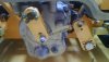
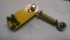
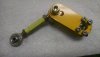
I was letting the rear of my car down from jack stands and inadvertently dropped it too fast and a pair of wood blocks that I was using as spacers to raise the jack travel higher slipped and the car fell about 6 inches. Wouldn't you know it- the jack stand hit the rearmost shift rod (actually a 3/4" OD tube) and bent it into a question mark. Arrggghhh. 
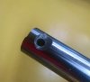
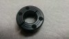
I had planned to replace it and one other part of my shift linkage anyway so that wasn't a complete disaster. I bought some Thompson Case 60 ground & polished rod a while ago for that purpose since the linkage runs in ball bushings. The problem started when I tried to drill the shaft for universal joint retaining bolts. A high speed drill would not touch it and neither would a cobalt drill. Not having a carbide drill, the hard surface of the shaft was resisting my attempts to drill a hole through the rod. Thompson says their surface hardness is 60 Rockwell C minimum and typically 62 RC.
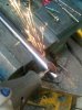
The solution was to grind off the hard outer surface on both sides of the rod, exposing the softer inner core. I used a Dremel tool with an abrasive and it worked very well. I was finally able to drill the through hole with an ordinary high speed #10 drill. Cutting the rod to length with a hacksaw was impossible but an abrasive cut-off disc worked just fine.
Regards, Neil Tucson, AZ
I had planned to replace it and one other part of my shift linkage anyway so that wasn't a complete disaster. I bought some Thompson Case 60 ground & polished rod a while ago for that purpose since the linkage runs in ball bushings. The problem started when I tried to drill the shaft for universal joint retaining bolts. A high speed drill would not touch it and neither would a cobalt drill. Not having a carbide drill, the hard surface of the shaft was resisting my attempts to drill a hole through the rod. Thompson says their surface hardness is 60 Rockwell C minimum and typically 62 RC.
The solution was to grind off the hard outer surface on both sides of the rod, exposing the softer inner core. I used a Dremel tool with an abrasive and it worked very well. I was finally able to drill the through hole with an ordinary high speed #10 drill. Cutting the rod to length with a hacksaw was impossible but an abrasive cut-off disc worked just fine.
Regards, Neil Tucson, AZ
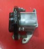
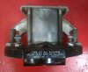


") In fact I just sold a 28VDC/115VAC 400Hz power inverter from an Apollo command module that I picked up in a salvage yard here in Tucson back in the early Eighties. It was from Apollo Boiler Plate #14. I bought all three inverters from the CMD; removing them was not an easy task.
In fact I just sold a 28VDC/115VAC 400Hz power inverter from an Apollo command module that I picked up in a salvage yard here in Tucson back in the early Eighties. It was from Apollo Boiler Plate #14. I bought all three inverters from the CMD; removing them was not an easy task.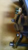
")