Southern GT #48

Neil

Supporter
Eddy, unless the load on the 10V output is very small, you may need to fasten the tab of your LM7810 regulator to a heat sink. The important parameter here is power dissipation, not its output current rating. Also, be aware that the tab is electrically "hot" so the heat sink will short to ground unless it is insulated from the tab by an anodized heat sink, an aluminum oxide washer, etc. Connecting the tab to the heat sink with a screw & nut is OK if you make sure he heat sink cannot make contact with a ground.

FWIW, the regulator power dissipation can be calculated by measuring the output current and multiplying it by the voltage drop across the regulator. Pd = Iout x (Vin - Vout) the units are watts, amps, and volts. On the LM7810 data sheet you will find its "Thermal resistance" rated in C/W (degrees per watt) from the junction to the case (tab) as Theta jc or to the free air temperature, Theta ja. If you mount the regulator on a heat sink, simply add Theta jc to the heat sink thermal resistance. To determine the regulator's internal junction temperature, multiply the Pd times the total thermal resistance and then add the ambient temperature since this calculation gives you the temperature rise above ambient. You need to keep its junction temperature well below 175C.
Example: LM7810 Theta ja = 5C / watt If the input voltage is 14V when your alternator is charging, then the voltage drop is 14V - 10V = 4V. Let's say you are supplying the load with 1A, then Pd = 4V x 1A = 4 watts. Then the junction temperature rise will be T = 5C / watt X 4 watts = 20C. The junction temperature (Tj) will be 20C + Ta, where Ta is the surrounding air temperature. At room temperature, Tj = 45C, a safe temperature.
HOWEVER, bear in mind that mounting the circuit in a small plastic box will thermally insulate the tab, allowing no air circulation, st the actual value of Theta ja will be higher. Also, the ambient temperature may be far higher depending on where the regulator is mounted in your car. These questions will be on the exam. :(
 

Ed McClements

Supporter
Eddy, unless the load on the 10V output is very small, you may need to fasten the tab of your LM7810 regulator to a heat sink. The important parameter here is power dissipation, not its output current rating. Also, be aware that the tab is electrically "hot" so the heat sink will short to ground unless it is insulated from the tab by an anodized heat sink, an aluminum oxide washer, etc. Connecting the tab to the heat sink with a screw & nut is OK if you make sure he heat sink cannot make contact with a ground.

FWIW, the regulator power dissipation can be calculated by measuring the output current and multiplying it by the voltage drop across the regulator. Pd = Iout x (Vin - Vout) the units are watts, amps, and volts. On the LM7810 data sheet you will find its "Thermal resistance" rated in C/W (degrees per watt) from the junction to the case (tab) as Theta jc or to the free air temperature, Theta ja. If you mount the regulator on a heat sink, simply add Theta jc to the heat sink thermal resistance. To determine the regulator's internal junction temperature, multiply the Pd times the total thermal resistance and then add the ambient temperature since this calculation gives you the temperature rise above ambient. You need to keep its junction temperature well below 175C.
Example: LM7810 Theta ja = 5C / watt If the input voltage is 14V when your alternator is charging, then the voltage drop is 14V - 10V = 4V. Let's say you are supplying the load with 1A, then Pd = 4V x 1A = 4 watts. Then the junction temperature rise will be T = 5C / watt X 4 watts = 20C. The junction temperature (Tj) will be 20C + Ta, where Ta is the surrounding air temperature. At room temperature, Tj = 45C, a safe temperature.
HOWEVER, bear in mind that mounting the circuit in a small plastic box will thermally insulate the tab, allowing no air circulation, st the actual value of Theta ja will be higher. Also, the ambient temperature may be far higher depending on where the regulator is mounted in your car. These questions will be on the exam. :(

Hi Neil, and thanks for your *input which is **warmly welcomed.

Unless I badly mis-read the datasheet of TO220-packaged L7810CV regulators, the tab is ground (along with centre pin). In fact, just hang on a tick....<sound fx - footsteps disappear into distance, clicking and scuffling sounds, footsteps returning>...yup, just tested it - the tab is ground.

The Caerbont / Smiths website seems to say that the 52mm gauges have a current draw of 100mA, and I wish to run two gauges per regulator, which makes the math 4V x 0.1A x 2 = 0.8 watts. I had originally planned to mount both 7810 regulators to an aluminium plate, screwed to the chassis somewhere behind the dashboard, but I liked the idea of encasing it within a relay body, and my quick calculations showed that temperature wasn't going to be an issue. My next step is to pop off the relay cover, hook up the device to a 12V supply, one fuel gauge and one sender (mostly to ensure calibration, tbh) and I'll check temperatures at that point (but I entirely take your point about input being nearer 14V while the alternator is spinning).

I believe (but have not confirmed) that mobile phone chargers which utilise the cigar lighter socket use a 7805-series regulator or similar to provide the 5V required to charge a phone, and while charging from low battery a phone draws about 0.7-0.9A. With the voltage drop from 14V to 5V, this would be 9V x 0.9A = 8.1W. This is a factor of ten greater than the power consumption of what I am attempting, and I'm pretty sure that the mobile phone chargers scarcely become warm.

Disclaimers:-
This is the first bit of electronics I have attempted; anything which doesn't need a 3/4" impact wrench or 4lb hammer is an anathema.
Your mileage may vary.
May cause reproductive harm.
Not legal in some states.

* and ** puns only slightly intentional.
 

Neil

Supporter
Eddy, you are right- the 7810 package tab is ground, not hot. I should have looked at the data sheet. :mad: That is opposite of most TO-220 transistors. Having a grounded tab makes heat sinking the regulator much easier. BTW, I think that most USB car chargers are switching regulators rather than linear. They are more efficient at higher current.
 

Ed McClements

Supporter
Not done much these last three weeks, but I did check that I have 10v out on two separate pins, so I can provide power to four gauges which need 10 volts - two fuel gauges, one oil temp and one coolant temp.

50699335722_29baffd3cc_o.jpg
 

Ed McClements

Supporter
@Mic @weisserheilbronn @Mark Boyers @davidmgbv8 Thank you all for the suggestions. I'll test the annealing you describe - trouble is it's a large-ish panel and I have little spare aluminium for tests / fails! Will let you know how I get on.

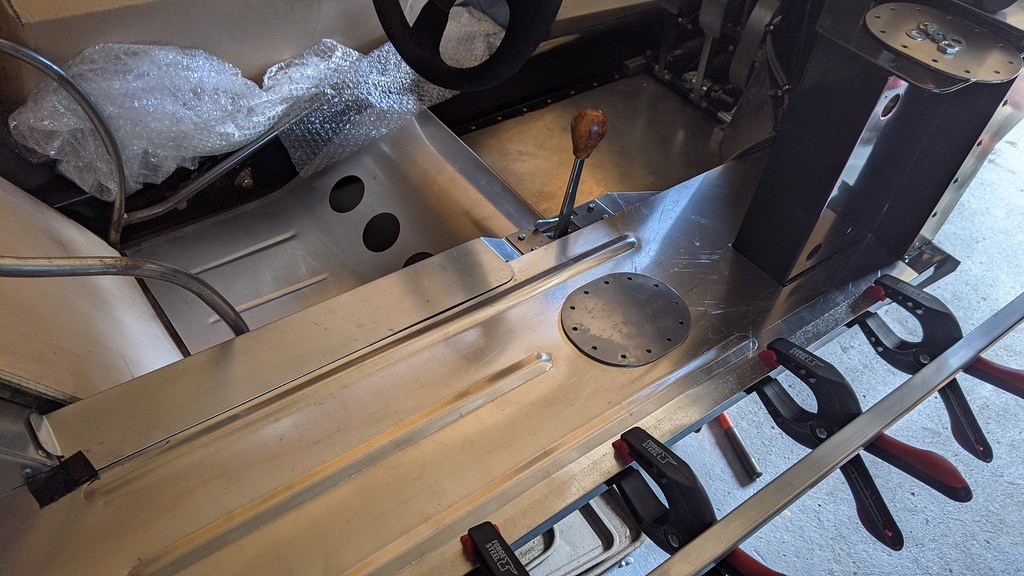
The (relatively) cheap bead rolling tools are hard to use - one hand turning the handle means one hand to guide the workpiece, with the inevitable wonky lines. To get round this while still working single-handed I made up some nylon guide pulleys and screwed them to some MDF sheet, as shown here:-

51097331605_c9e764a4ce_o.jpg


51097070448_042093bca0_o.jpg


And, even better, my attempt at annealing (Sharpie marker, propane torch) means that I haven't ended up with a Taco shell / Pringle (delete as appropriate for your region).
 

Ed McClements

Supporter
Friday was bracket day...

IMG_20210129_103529

IMG_20210129_135019

IMG_20210129_173036

IMG_20210129_173333

IMG_20210129_174219

IMG_20210129_174659

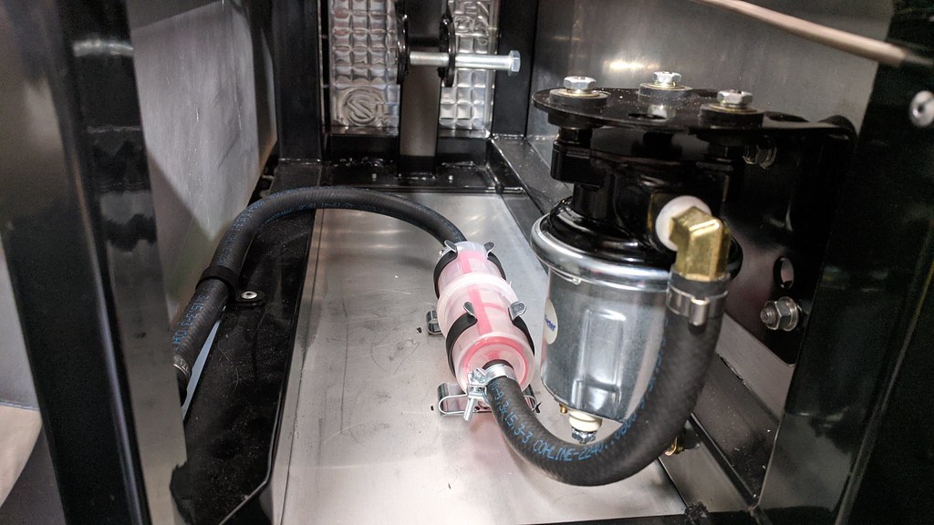
The Malpassi regulators will be fed by two of these Carter P4600 pumps...one each side, as near to being level with the tank outlets as I could mount them.

IMG_20210114_173319

Gauze filter to catch any swarf or crud, then the pumps (one each side) will feed a filter/regulator, then each will have a non-return valve (so that running one pump won't feed back to the opposite tank) then T'd together to the carb...or carbs.

Edited to add:-

There will be a normally-open solenoid between the feed to the carb, and a return to the left-hand tank. When the ignition is on, this valve will close, allowing fuel pressure (6-8psi, according whichever carb is selected) to build up. When the ignition is switched off or power is cut, the solenoid valve will open, dumping any remaining pressure back to the tank. This is just so that any remaining fuel in the feed line to the carb doesn't gradually leak past the float needle valve and trickle into a hot engine.
 
Last edited:
Hi Eddy,
Really like what you’ve done with your bead-roller. I bought a similar one for the panelling on another ’40 I’m building. There’s various clips on You-tube how to use & improve these rollers, but I found by modifying it to use a 3/8” ratchet instead of the drive handle, I found a lot easier to control, especially on long straight runs.
I also made a set of dies that would do a 1” rib in a single pass, which work really well for the sill top ribs and then added this feature to a couple of the other panels. The radiused ends of the rib were formed with a separate press tool. A single step tool was used to add the feature to the bulkhead access panel
Regards,
Revised handle.jpg
Custom Dies.jpg
Off-Side Sill inner.jpg
Front Access.jpg
Engine Access Panel 1.jpg

Andy
 

Ed McClements

Supporter


Hi Andy

I see you have had the same problem as me...lack of rigidity!*

I clamped a couple of hefty alloy blocks either side of the upper & lower jaws to reduce the throat of the roller to the minimum where I could still fit the workpiece into place - this helped a lot. Prior to that, the upper roller would advance ahead of the lower roller, twisting the flimsy 10mm sheet steel plate and drawing the bead off-line.

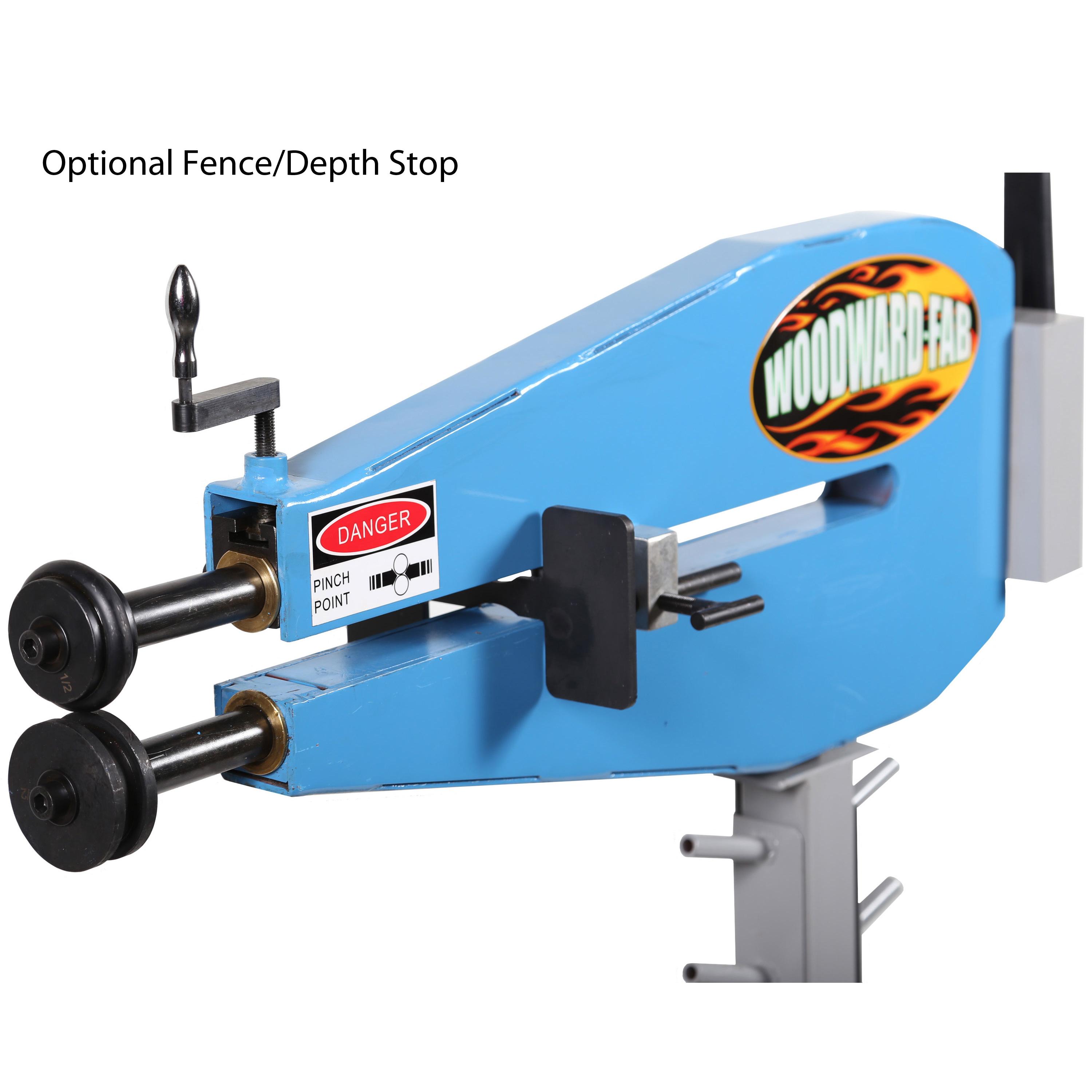
If I do much more of this I might box-in the shafts, like the better versions of the commercial tools:-

woodward_fab_wfbr24p_Bead_Roller_06.jpg


That bulkhead of yours is really something...!

*No...not that lack of rigidity. That still works fine, thanks.
 

Andrew

Supporter
Really glad to see some progress on the build, I'm watching with interest the fueling system come together too

I cut the handle off and fitted a steering wheel to my bead roller, made a world of difference! Can be seen in the video below, skip to 9:25

 
Last edited:
I also have the cheap one, but it has issues doing 12 gauge (5/64 or 2mm) aluminium. Even after annealing it.
Not sure which grade alloy sheet I am using. Its industrial stuf suplied localy by a welding shop.
 

Ed McClements

Supporter
Large trucks use thin stainless steel straps to secure their fuel tanks and a rubber liner cushions the tank. You might have a look:


Hi Neil

I think that suggestion is intended for Andrew's Tornado project; he has his own thread...


My tanks are Southern GT and are bolted-in using their own flanges / brackets.

Cheers,

Eddy
 

Ed McClements

Supporter
Sorry for the "radio silence". Change in personal circumstances mean that I haven't touched the car for a year. During that time, Mick has fully retired and sold Southern GT, and I need to re-plan the budget (or lack thereof).
 
Back
Top