For various reasons I have not reported any significant progress on my project this year yet, but I'm hoping that will change now that I am over the hurdle of the rear uprights. This turned out to be a very long story which needed facilities that I do not have in my garage and took a lot of running around to sort.
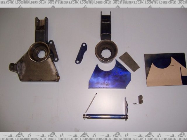
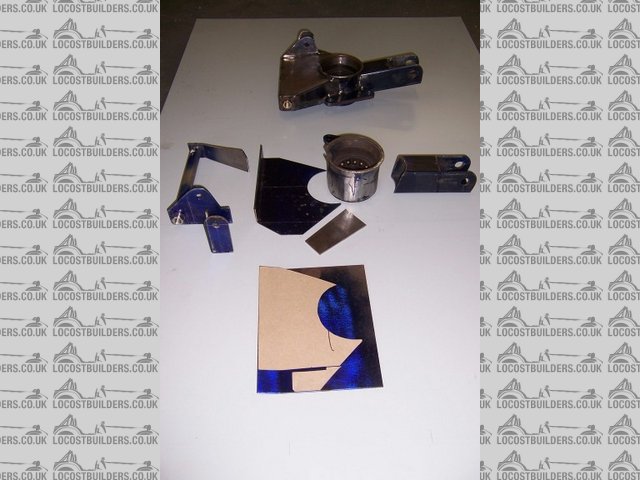
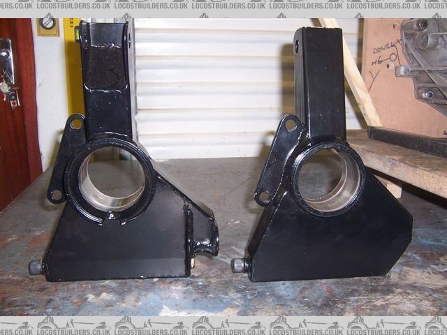
I started to fabricate these around the bearing housings cut out of the front struts from the Audi that donated the transaxle. In these picture you can see the parts and a tube that self jigs the lower bushes in line with each other and the side walls vertical.
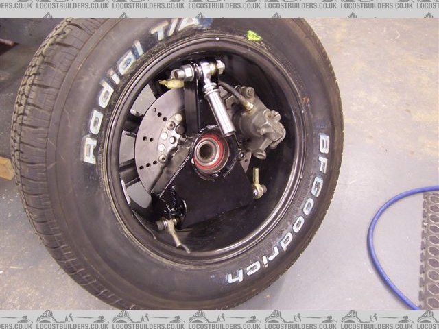
I intend to make the real wishbones from 21.3 od x 2.11wt Schedule 10 stainless tube, with machined inserts plug and fillet welded into the ends. You can see the detail in the pic below. I have also used this detail inside the bottom of the uprights. Joints are M12.
I tacked the parts together and took them to a friend (man 1) to be TIG welded up. I left the old bearings in in what turned out to be a vain hope that they would help prevent the housings distorting too much. Getting the old bearings out was difficult, this was eventually only accomplished with the aid of a big press and welding on the race by a car repair shop (man 2 and 3). The housings were up to 0.5mm out of round in places.
So this needed to be sorted. I bought new bearings to measure from a friend at a bearing suppliers (woman 4) who recommended a workshop that might be able to help (man 5). Talked to man 5 who took an interest in my project, but could not help and suggested I go to a machine shop nearby (man 6). Man 5 even phoned man 6 to tell him to expect me. Man 6 turned out to be the proprietor of a fair size industrial machine shop and who also builds and races V8 dirt track cars as a hobby. He told me to leave the housings with him.
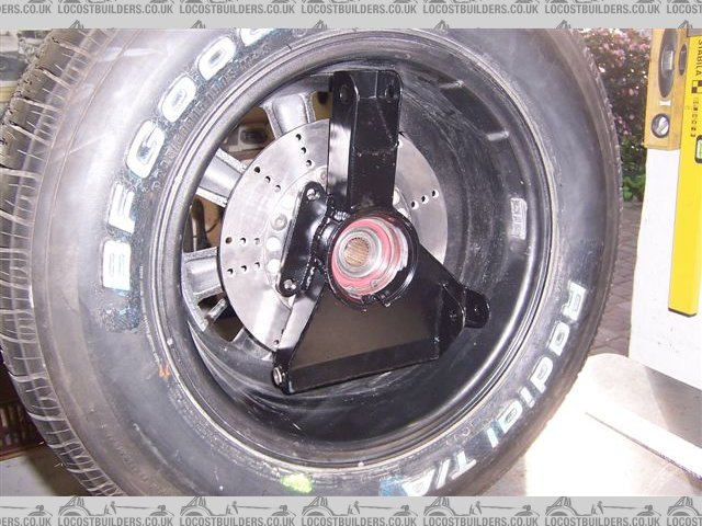
In the meantime I had drilled the hubs to convert to Ford PCD and studs, which necessitated visits to another friend (man 7) to use his small lathe to cut the "as cast" rear face of the hubs and then back to man 1 to press in the new studs.
Man 6 called to say the uprights were finished. He had cut a true reference step in one end of the housings, made a fixture to hold the uprights in a lathe, turned them to a true size and matched them to the bearings. He refused to accept any payment for all of this.
So now I could take the uprights home to fettle some of the welding a little and then to a paintshop (man 8) to have them sand blasted and painted black.
Then back to man 6 who light press fitted the bearings and hubs and finally I could test fit the brakes and see how they looked in the wheels.
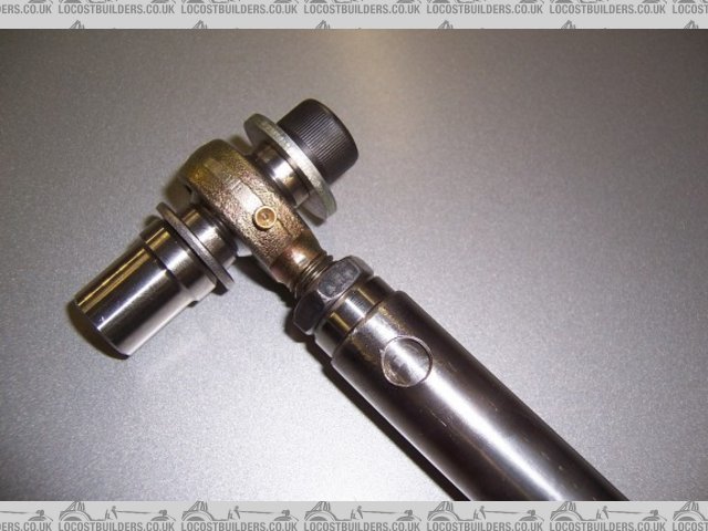
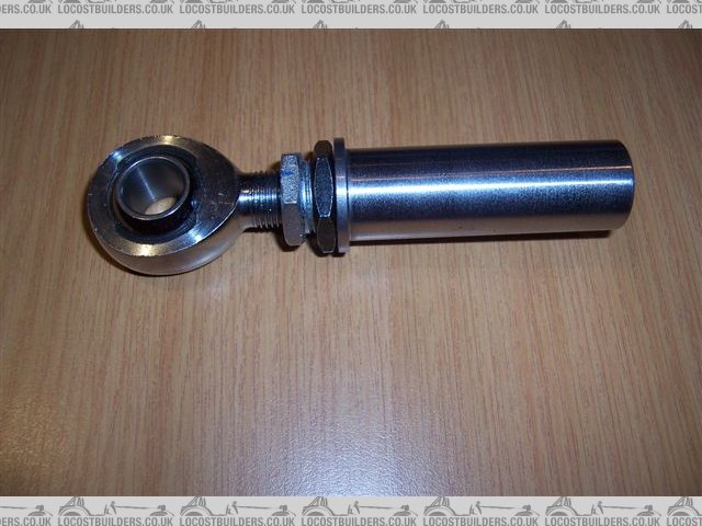
The top M16 attachment incorporates a internal and external threaded bush between the left hand 1.5 mm threaded rose joint (sourced from McGill motorsport U.K.) and the bush that will be welded into the top wishbone to give camber adjustment. A 360 deg rotation gives 3 mm of movement. The black half nut is the locknut on this adjustment bush, the lock nut on the rosejoint is not fitted yet. These parts were sourced with help from yet another friend (man 9).
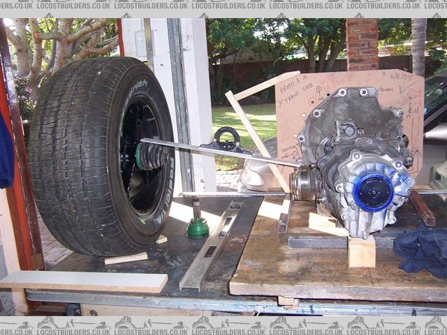
And finally I could mock up the wheel to trans axle geometry assembly. With a rear ride height of 125 mm It looks like I will get just on 10 deg drive shaft angle.
Cheers