Charlie Farley
Supporter
Belt & Braces job Fran.
There are inherent fallibilities with old designs....you can only do so much.
There are inherent fallibilities with old designs....you can only do so much.

Thanks for your insight jac
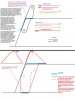
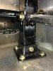
The brackets we already offered spread the load onto another much larger surface area and a plane perpendicular to the mounting surface of the primary turret mount helping to distribute the load down to the floor of the monocoque, larger than even you suggest necessary. This area of the floor also has internal bracing that creates the bulkheads inside the torque box area of the engine bay.
The "new bolt on brace" also create a cap over the top of the turret to help prevent runaway radius rods from cockpit intrusion which the modification done to Craig's chassis do not appear to have. This type of cap/safety option does not appear to be used on many other radius rod suspension style cars, real or replica, obviously an oversight on everyone's behalf , including mine especially in the modern world of more readily available and powerful engines ,stickier tyres and better brakes.
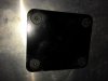
My Lola continuation spyder has a small 0.040 plate closing off the front of original design turret but it is not welded in place , only buck riveted. This is obviously acceptable as a period type modification , but without that the rod would be capable of direct cockpit intrusion with only a fiberglass bulkhead as protection .
The RCR bracing brackets offered FOC are also steel 0.090 not Ali as the prototypes are shown and require no welding to install .
Thanks for your insight jac
The brackets we already offered spread the load onto another much larger surface area and a plane perpendicular to the mounting surface of the primary turret mount helping to distribute the load down to the floor of the monocoque, larger than even you suggest necessary. This area of the floor also has internal bracing that creates the bulkheads inside the torque box area of the engine bay.
The brackets do both Jac
Brace the turret and also create a captive cap
I am in vacation in the south of France with my family so any reply I make is out if sight and earshot of the missus
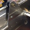
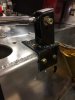
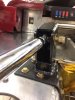
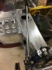
The welds look like they didn’t penetrate the tube. The metal under the wields was still intact. If the welds had melted the internal ply, then you’d get a crack through the entire material.I was running my RCR Lola at a track day at the Circuit of the Americas on July the 5th. Under braking up the front straight entering turn one, the right rear control arm mount tore out of the chassis causing a severe toe-out on that wheel sending the car into a slide. I brought it to a safe stop off track. The car was running Dunlop Vintage hard compound bias-ply treaded tires, not a full slick, so the braking stresses were not extraordinary. My telemetry was showing 1.1-1.2gs average braking force around the track.
You can see in the attached pictures that the pressure on the area caused the aluminum sheet around the mount to distort before the weld failed. This chassis has 2,000 road miles on it and a total of 60 laps at COTA completed at 3 track events prior to the failure.
I am posting this for informational purposes only. I waited to see if the manufacturer would provide the information and specific recommendations to the owners of these chassis. I felt an obligation, in the absence of any notice, to recommend that all owners have these locations inspected and crack checked periodically.