Chassis Failure

flatchat(Chris)

Supporter
How did that bit (trailing arm post) break again ?
Looks to me as if it were a substantial shunt from the rear
Or being airborne for a moment -hard on the gas and hitting the tarmac while travelling backwards
 

Pat

Supporter
I understood from Glenn's original post, the mount failure came as a result of heavy braking on the racetrack, not a shunt.
I located some additional LOLA photos from Bill Thumel's beautiful T70. He has the control arm mount integrated into the roll bar structure. Seems like a good way to reasonably minimize the risk of becoming a suspension-kebab.
 

Attachments

  • BillThumel-Lola-T70-CC.jpg
    BillThumel-Lola-T70-CC.jpg
    89.5 KB · Views: 847
  • BillThumel-Lola-T70-CK.jpg
    BillThumel-Lola-T70-CK.jpg
    62 KB · Views: 781

Fran Hall RCR

GT40s Sponsor
Robert
You are correct
There are also welds inside the engine bay sponson
That attach the turret to the back of the seat back -transom not just tack welds as jac theorizes. As for the panel flexing around the access home , that panel is 0.250 thick with diagonal one inch bracing welded across it's surfaceSo once the 0.250 cover panel is bolted in place it's a pretty substantial panel and nothing like as flexible as jac fears
Veek that still really doesn't stop the radius rod from pushing forward should the rod end break and the bulkhead is only fiberglass between the engine bay and the cockpit on an original Lola
 

Attachments

  • image.jpg
    image.jpg
    48.5 KB · Views: 755
Last edited:

Pat

Supporter
Robert
Veek that still really doesn't stop the radius rod from pushing forward should the rod end break and the bulkhead is only fiberglass between the engine bay and the cockpit on an original Lola

Fran, as I see it, the structure on Bill Thumel's car puts the roll bar between the control arm and the driver in addition to the more robust mount. The original GT40 structure is steel with diagonal rigidity distributing the shear force from the engine mount to the firewall. It includes a flange on the end of the mount. Both put steel between the driver and the control arm.
 
Last edited:

Fran Hall RCR

GT40s Sponsor
Veek
Our mounts are made from 1/4 inch 5052 material which is more than strong enough and significantly stronger than 0.040 -0.060 thick steel used in a Lola or a gt40
 
Here's a pic of my RCR after the crash Fran referred to.
The suspension had been reengineered by Greg Bailey as we had identified the risk of the locating arm punching through into the drivers back and relocated it onto a steel mount on a lower crossmember of the roll bar. The locating position was also relocated slightly following a suspension analysis by Greg. (This image is a bit lo-res, sorry, the location is on the crossmember under the catch tank)
 

Attachments

  • lola wreck 2012-07-21.jpg
    lola wreck 2012-07-21.jpg
    223.8 KB · Views: 960

Fran Hall RCR

GT40s Sponsor
Post some pictures Craig so Glenn can see
And maybe Peter Baileys comments about the strength of the chassis
Don't think Flatchat has made any changes to his car and he too has had a couple of dings due to some modern Porsche drivers from memory
Thanks
 

Glenn B.

Lifetime Supporter
Craig,

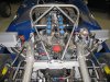
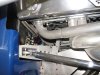
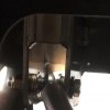
I would be very interested to see images of the modifications you and Greg Bailey made. You and he appear to share our concern for driver safety.

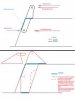
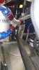
Your photo validates my point: Your use of stronger steel in the mounts than the control arms, and isolating them from the driver's compartment resulted in the energry transfer from the impact to be contained within the suspension pieces, causing the steel control arms to bend. The proposed solution of bolting the control arm mount to the aluminum seat back would have transferred that same energy load directly to the driver's back, instead. The flat aluminum plate of the seat back would fail before the steel control arms would have bent. In this scenario, the control arm would not have needed to snap and penetrate the cockpit to injure the driver. The amount of distortion we can see in your steel suspension components would have been the minimum amount of movement of the seat back panel into the driver at a very high and concentrated G-load caused by the impact.

Testimonials, discussions of thicknesses and robustness of materials, and comparisons to 49 year-old designs don't change the fact that this particular combination of design, materials and their installation (use of welding) failed when in real world use, at low G forces, without the presence of an impact.

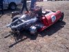
Upon examination after the failure, we came to the same conclusion Craig Cumming and Greg Bailey: that these components of the chassis need a complete redesign to be both strong and safe. If anything, Craig's shunt is a testimony to the integrity of their redesign work. Even under the force of a severe impact, their redesigned mount didn't fail and the driver's compartment wasn't compromised. Well done. We are looking forward to seeing your work.

Thanks,

Glenn
 
Last edited:

Fran Hall RCR

GT40s Sponsor
Sorry Glenn I disagree that the design needs a complete overhaul but that's an argument neither of us will win.

My comments about material strength are very pertinent and applicable

Our gt40 has an alum bulkhead between the engine bay and driver compartment but the Lola does not.

This topic has been discussed previously with owners of real and replica cars and the only real solution is to not use radius rod suspension at all and use unequal length control arms as the new ford gt does.

As I said previously we are more than willing to help any of our customers if they want to contact us directly, I will gladly develop a bolt on steel cap to contain the radius rod and supply it to any owner that wants a pair, I leave for vacation in two days but will make sure this part is designed before I leave to ease anyone's concerns .

Glenn .How many track days/sessions/miles do you have on the car currently ?
 
Last edited:

Glenn B.

Lifetime Supporter
Approximately 2,000 total miles comprised of street and highway driving (no street or drag racing, burn outs, etc...I don't believe in it.)

Within that total, 2.5 Track sessions were run at the Circuit of the Americas (the third being cut short by the chassis failure), for a total of ~60 Laps (~200 total miles) on track including warm-up and cool down laps. The car is not raced competitively.
 

Glenn B.

Lifetime Supporter
That... and a few of my other "toys" until we get the the Lola fixed and get in back in the stable. I enjoy driving it as much as any of my other cars.

I have 4 vintage races between now and November in Colorado, Oklahoma, Texas and Louisiana, so the Lola will have to sit for now and be a winter project.
 
If I had the misfortune to own one of these I would replace the factory bracket as drawn at top and fabricate / fit something along the lines of the lower drawing, gets rid of the potential for flex/wriggle the original setup has and spreads the loads over a greater area. Was looking at the pics of an original tub in restoration and while they might be made of thinner steel etc, the top and bottom pickup points feed the loads into a much larger area of the monocoque.
 

Attachments

  • Untitled.jpg
    Untitled.jpg
    7.9 KB · Views: 675

Fran Hall RCR

GT40s Sponsor
Cheeky bugger and thanks for your thoughts and insight.

I have already started on the design of the bolt on steel bracket that spreads load over a wider area than an original Lola or GT40 !!
You assumption for the shape of my original
Bracket is incorrect btw but hey you are JacMac the unfortunate

I will measure my original 1969s T70 3b suspension mount and also my continuation mk3 spyder tomorrow and compare them and the footprint to mine and publish findings.
We did run a lot of FEA on the chassis design and do so for all of our products btw
 
Last edited:
Just as well you can edit your posts Fran, at one stage last night I was tempted to ask if you were drunk, rambling on about spades, space shuttles etc... Have a nice time designing your brackets etc , oh what a difference a day makes :):)
 

Fran Hall RCR

GT40s Sponsor
I said yesterday that we would take care of any of our customers that want to call and be at ease so nothing changed there.
Actually it was the middle of the night 4am ish I think
I was waiting for a plane and working from my phone whilst half asleep ,then lost signal during the flight as I am too cheap to pay for wifi on the plane....still half asleep but at least I am not travelling for another two days...
 
Last edited:

Ron McCall

Supporter
FWIW, I ran my RCRGT40 for WAY more than 2000 miles and MANY track miles ( VIR, Pocono,Summit Point, NJMP etc...) with 700hp , AP brakes and always ran sticky race tires and never had any sort of issues and constant inspection revealed no sort of failure of the chassis whatsoever. Including a pretty solid "off" when I had a Wilwood brake balance bar fail going into turn 5 at Summit Point.

Ron McCall
 
Glenn,

Heres a close up pic of our revised front mount that survived the backwards into the armco crash. Its lower than original following a geometry review.

Jacmac,

I have no regrets regarding having gone for the RCR car. The chassis basically needed dusting off following a crash that would have left a space frame a write off and an original or original tub replica needing a huge amount of work.
As with everything its not perfect and details can be improved on.
 

Attachments

  • DSC_0591 reduced.jpg
    DSC_0591 reduced.jpg
    74.5 KB · Views: 802

Fran Hall RCR

GT40s Sponsor
Anti-intrusion chassis brace

Here you go fellas...as promised before I hop on a plane for my family vacation this afternoon.

Developed to relieve concerns about an age old problem with rear radius rod suspension cars with the potential for the rod to enter the cockpit during an accident.
They also have the additional benefit of providing more strength to the suspension turret.
These are a bolt on component that will fit any monocoque chassis we have built in the last ten years.


It should be noted that we have never had this happen and it would need a "perfect storm" scenario for it to happen, but better safe than sorry.

These will be available to ship mid next week once welded and cad plated.

They are available to anyone that has an RCR replica monocoque free of charge.

Please contact Vicki at the shop
 

Attachments

  • photo 1 [640x480].JPG
    photo 1 [640x480].JPG
    39.7 KB · Views: 699
  • photo 2 [640x480].JPG
    photo 2 [640x480].JPG
    40.4 KB · Views: 610
  • photo 3 [640x480].JPG
    photo 3 [640x480].JPG
    42.3 KB · Views: 738
  • photo 2a [640x480].JPG
    photo 2a [640x480].JPG
    45.7 KB · Views: 616
  • photo 4 [640x480].JPG
    photo 4 [640x480].JPG
    43.5 KB · Views: 684
  • photo 1a [640x480].JPG
    photo 1a [640x480].JPG
    40.3 KB · Views: 661
Last edited:
Back
Top