Glenn B.
Lifetime Supporter
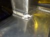
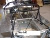
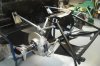
I was running my RCR Lola at a track day at the Circuit of the Americas on July the 5th. Under braking up the front straight entering turn one, the right rear control arm mount tore out of the chassis causing a severe toe-out on that wheel sending the car into a slide. I brought it to a safe stop off track. The car was running Dunlop Vintage hard compound bias-ply treaded tires, not a full slick, so the braking stresses were not extraordinary. My telemetry was showing 1.1-1.2gs average braking force around the track.
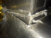
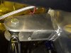
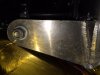
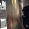
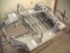
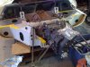
You can see in the attached pictures that the pressure on the area caused the aluminum sheet around the mount to distort before the weld failed. This chassis has 2,000 road miles on it and a total of 60 laps at COTA completed at 3 track events prior to the failure.
I am posting this for informational purposes only. I waited to see if the manufacturer would provide the information and specific recommendations to the owners of these chassis. I felt an obligation, in the absence of any notice, to recommend that all owners have these locations inspected and crack checked periodically.