Pardon my over active brain cells, but if you do a positive 'g' pull-up or steep turn in flight the fuel pressure in the lines will increase during that time, however you probably DO NOT want to apply ~12psi to the tanks, just the lines/fittings. BTW the 12psi is just a guess on my part, don't take it as a suitable number.

You are using an out of date browser. It may not display this or other websites correctly.
You should upgrade or use an alternative browser.
You should upgrade or use an alternative browser.
Chuck and Ryan's Carbon Cub Build Blog
- Thread starter CESLAW
- Start date
Chuck, is it worth getting a tape and marking a known length on the ballon? Then that can be measured at a later date. Better than guessing if it has gone down a bit?
What Jac Mac is saying is worth a thought here. I would think attaching a pressure gauge(on a compressor) on one of the lines and apply the amount of pressure that a high G turn would exert(bar). Then do the outside soapy water test. You could get one of the water pressure gauges that home depot has to test your homes water pressure for instance. Not sure how these would be connected(adapted) but a thought.
Bill
Bill
Ian Anderson
Lifetime Supporter
Or a radiator pressure tester adapted for the job. Pump to XXX psi and leave it connected and see if the gauge drops ove time
Like this
Radiator Pressure Tester Kit
It would allow you to check above a couple of Psi which is all a baloon will hold
Ian
Like this
Radiator Pressure Tester Kit
It would allow you to check above a couple of Psi which is all a baloon will hold
Ian
You could try the baloon test using Helium. The smaller molecules will escape through a leak faster than air. Only problem, is the He will also escape through he baloon faster than air to, so you should set up a separate ballon as a control so you can see if the isolated balloon stays full longer than the ones on your line.
..May be more trouble than its worth if you don't have access to He.
..May be more trouble than its worth if you don't have access to He.
Thanks for the feedback. I find it interesting that there is more feedback on this airplane build on this site than at SuperCub site. Just goes to show that GT40 types are better engineers!
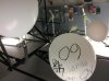
Jac: interesting point I had not considered. The psi at the engine fuel pump in this high wing gravity feed system is about 1 psi in level flight. So if we actually pulled 3 g's the psi would still be low. Likely less than what the four inflated balloon are exerting now.
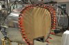
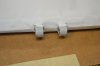
We are now out about 90 hours and the balloons are still holding air. If there were even a tiny leak it would seem the balloons would have deflated by now.
The cheap balloons lose air over time and barometric pressure can change the size as well. Marking them with a measurement would document these changes. But since we are only seeking to determine if it will hold pressure over time, the longer it holds air the less critical such a precise measurement would be.
The coolant system pressure system is a good thought. I used that same system on the GT. It would take some doing to get matching fittings.
So at this point I am pretty confident the system is leak free.
Really good ideas! Thanks
Jac: interesting point I had not considered. The psi at the engine fuel pump in this high wing gravity feed system is about 1 psi in level flight. So if we actually pulled 3 g's the psi would still be low. Likely less than what the four inflated balloon are exerting now.
We are now out about 90 hours and the balloons are still holding air. If there were even a tiny leak it would seem the balloons would have deflated by now.
The cheap balloons lose air over time and barometric pressure can change the size as well. Marking them with a measurement would document these changes. But since we are only seeking to determine if it will hold pressure over time, the longer it holds air the less critical such a precise measurement would be.
The coolant system pressure system is a good thought. I used that same system on the GT. It would take some doing to get matching fittings.
So at this point I am pretty confident the system is leak free.
Really good ideas! Thanks
Attachments
Chuck, just something to think about but worth noting - The aircraft is not, obviously, a static machine, meaning as it flies it will twist, turn and vibrate with stress and engine speed. To me it would make sense to pull/push (or at least try to) on the fittings a bit to simulate active stresses while flying - just sitting there doesn't do that. Or, you could just take her up and if you smell gas, bring it back down :stunned:
AJ
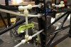
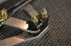
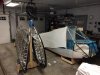
Good thought. But this plane uses flexible plastic tubing for the fuel lines rather than rigid aluminum. At first this struck me as odd, but the advantages are several, one of which is metal fatigue won't be a problem since it flexes a bit.
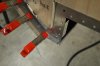
Once the fittings are finger tight, they are turned twice more with a wrench. They are really tight. Than a plastic sealant is applied which makes it impossible to twist off the fitting. Finally all the tubing is covered with a protective wrap (similar to the painless wrap I used on the GT electrical wires).
Looks like a pretty solid, durable system.
Finally, about a 100 hours out and the balloons are still holding air . . .
Good thought. But this plane uses flexible plastic tubing for the fuel lines rather than rigid aluminum. At first this struck me as odd, but the advantages are several, one of which is metal fatigue won't be a problem since it flexes a bit.
Once the fittings are finger tight, they are turned twice more with a wrench. They are really tight. Than a plastic sealant is applied which makes it impossible to twist off the fitting. Finally all the tubing is covered with a protective wrap (similar to the painless wrap I used on the GT electrical wires).
Looks like a pretty solid, durable system.
Finally, about a 100 hours out and the balloons are still holding air . . .
Attachments
Chuck,
You will have to forgive me but that tubing looks just like the stuff from Home Depot:stunned:
Bill
You will have to forgive me but that tubing looks just like the stuff from Home Depot:stunned:
Bill
Terry Oxandale
Skinny Man
Fascinating build. Enjoying this as much or more than the automotive builds.
Fascinating build. Enjoying this as much or more than the automotive builds.
It is a cool build, can't wait for the flight videos!
After this is done, Chuck and Ryan can build one of these;
For Sale
It is definitely the GT40 of the skies!
Nah!! I think Chucks next project should be one of these:
https://www.youtube.com/watch?v=D7-lUBm-Guw
Bill
https://www.youtube.com/watch?v=D7-lUBm-Guw
Bill
The Boot Cowl
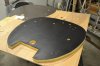
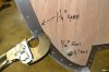
1. Before any rivets are placed on the fire wall, we used the fire wall as a pattern to cut out the black vinyl and fiberglass insulation. We used the fire wall as a pattern to cut out each of the holes with a #11 Exacto knife. Once all the holes are neatly cut, we glued the vinyl to the fiberglass with 3M spray adhesive. Then we set it aside. The fire wall was also used as a pattern to mark an outline on a 4 x 4 section of birch veneer plywood.
2. We measured 1 ¼ to 1 ½ inches inside the outline of the fire wall on the board so there would be enough space to clear the out squeeze riveter and then we cut it out. Even cutting it back that distance proved insufficient and we ended up grinding a bit off the rivet squeezer.
3. When placing the fire wall / plywood on the fuselage we discovered that the top of the heater vent on the floor board was interfering. It was trimmed back even with the fire wall. Four hardware store 5/16” bolts were used to hold it in place, ready to add the side panels.
4. The temporary instrument panel was installed with those frustrating Adel clamps per the award winning Mitch Travis video. We discovered that the lateral position of the panel is important and can make a difference in the way the support tubes center in the openings. The holes for mounting the panel were elongated so that we could precisely locate it evenly left to right, marking a reference point and then measuring on both sides. A tiny lateral variation in the location of the panel can make a difference in the alignment of the two support tubes in the cowl openings.
5. Use lots of clips. We placed a clip between every rivet hole. Start the clips at the bottom so that the angle at the bottom of the cowl is exactly even with where the tunnel will be. Odds are by the time you get done working your way to the top with those clips the top center seam will come together nicely. Likewise when placing the spacer strips, start at the bottom at the angle. This will result in a better fit at the bottom.
6. The gascolator cover went together just fine until we went to place the six Tinnerman nuts. None fit. On Mitch’s award winning video the Tinnerman nuts referenced were part number A1785-6Z-1D. Those are also shown in the pictures in the manual, although the manual references part number A1784-6Z-1 which is what came with the kit. So we called Wick’s and spent three bucks for the longer A1785-6Z-1D nuts, which worked just fine. Alternatively one could notch out the panel a bit so the supplied nuts would fit. I admit it. I’m lazy.
Attachments
Throttles
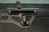
I used four washers separating the long Delron spacer bars. These don’t set the tension / friction, so the nuts were snugged tight. The connecting rod between the front and rear throttles was painted black before it was installed after roughing it up with a 3M Scotch Brite pad and wiping with denatured alcohol.
The tension is set with the bottom pivot screw on the forward throttle. A fish scale was used to get the 1 pound, six ounces of tension. I used only the forward pivot screw to set the tension.
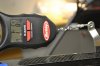
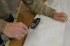
Now here is the cool part. We wanted a way to lock that nylock nut in place so the tension/friction could be adjusted easily with just a Phillip’s screwdriver from the pilot’s seat. An AN970-3 washer was modified by folding up two edges to lock the nut and folding down the other two edges to lock the D support that it sets upon.
After marking the fold lines, a “V” shaped grove was filed on the washer to assure a clean straight bend on the side opposite the fold. The finished folds were solid despite the material that had been filed away. Just to be sure, however, Ryan ran tiny TIG weld beads along each seam. A few minutes were spent filing the surfaces smooth and after a coat of black paint the job was done. Works perfectly and will make adjusting the friction / tension so much easier.
I used four washers separating the long Delron spacer bars. These don’t set the tension / friction, so the nuts were snugged tight. The connecting rod between the front and rear throttles was painted black before it was installed after roughing it up with a 3M Scotch Brite pad and wiping with denatured alcohol.
The tension is set with the bottom pivot screw on the forward throttle. A fish scale was used to get the 1 pound, six ounces of tension. I used only the forward pivot screw to set the tension.
Now here is the cool part. We wanted a way to lock that nylock nut in place so the tension/friction could be adjusted easily with just a Phillip’s screwdriver from the pilot’s seat. An AN970-3 washer was modified by folding up two edges to lock the nut and folding down the other two edges to lock the D support that it sets upon.
After marking the fold lines, a “V” shaped grove was filed on the washer to assure a clean straight bend on the side opposite the fold. The finished folds were solid despite the material that had been filed away. Just to be sure, however, Ryan ran tiny TIG weld beads along each seam. A few minutes were spent filing the surfaces smooth and after a coat of black paint the job was done. Works perfectly and will make adjusting the friction / tension so much easier.
Attachments
Fuselage Done
It has been a while since I posted an update here, although many details can be found at Chuck and Ryan's Carbon Cub Build Blog - Page 4 and Chuck and Ryan's Build Tips
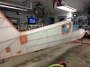
The fuselage is now covered. Hope to start covering the wings shortly. Here are a few highlights.
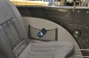
Map Pockets
After a lot of searching and ordering some that did not measure up to their advertising, we found storage pockets that look like they are up the Carbon Cub standards. They are made in Italy. One is curved, making it a perfect fit for the rear of the seat. The other is flat, 14” x 7”. Installing them required careful measurement to avoid hitting any vital organs with the holes were drilled. These will come in very handy.
Fabric
Once the mechanical work was done, it was time to mask the fuselage to prepare for fabric and paint. I though masking would take just a couple of hours. It took 10.
Fabric application was a new experience. The chemicals used are a bit noxious, but the one that really got me was the MEK, a solvent used for several purposes. I quickly discovered that one must use a respirator when using that stuff.
A rotator was purchased: a bit pricey but specific to this airplane. It really made working on the fuselage so much easier. It will also be used for the wings. When the plane is done it will be up for sale so we should recoup our investment. If I ever do a frame up car restoration, a rotisserie would be a must have item.
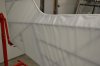
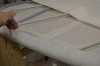
With the fabric applied there were lots of wrinkles. I had some doubts about whether they would all iron out, especially at the curve at the base of the rudder. With the first 250^ iron they all pretty much disappeared. With the 350^ iron the fabric was a tight as a drum. Cool.
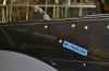
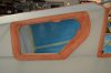
Baggage door
The opening around the baggage door required some extra steps to assure the stretching of the fabric would not interfere. This represents many hours of work but it came out exactly the way we intended. The pink stuff is “poly brush” which is a sealer adhesive applied over all the seams where a second layer of fabric is used. It will eventually be sprayed on the entire plane as the first sealer coat.
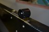
Throttle Knobs
The stock throttle knows are little round balls. Rather pathetic actually. Several Cub type planes add a PTT switch to the throttle knobs as well. So we decided to make our own.
Ryan milled several throttle knobs from both Delrin and aluminum. He powder coated a couple of the aluminum satin black. They look good. And they are much more manly than the girly knobs that came with the kit. We will offer them for sale to other builders.
The Fuselage is covered and now on to the wings.
It has been a while since I posted an update here, although many details can be found at Chuck and Ryan's Carbon Cub Build Blog - Page 4 and Chuck and Ryan's Build Tips
The fuselage is now covered. Hope to start covering the wings shortly. Here are a few highlights.
Map Pockets
After a lot of searching and ordering some that did not measure up to their advertising, we found storage pockets that look like they are up the Carbon Cub standards. They are made in Italy. One is curved, making it a perfect fit for the rear of the seat. The other is flat, 14” x 7”. Installing them required careful measurement to avoid hitting any vital organs with the holes were drilled. These will come in very handy.
Fabric
Once the mechanical work was done, it was time to mask the fuselage to prepare for fabric and paint. I though masking would take just a couple of hours. It took 10.
Fabric application was a new experience. The chemicals used are a bit noxious, but the one that really got me was the MEK, a solvent used for several purposes. I quickly discovered that one must use a respirator when using that stuff.
A rotator was purchased: a bit pricey but specific to this airplane. It really made working on the fuselage so much easier. It will also be used for the wings. When the plane is done it will be up for sale so we should recoup our investment. If I ever do a frame up car restoration, a rotisserie would be a must have item.
With the fabric applied there were lots of wrinkles. I had some doubts about whether they would all iron out, especially at the curve at the base of the rudder. With the first 250^ iron they all pretty much disappeared. With the 350^ iron the fabric was a tight as a drum. Cool.
Baggage door
The opening around the baggage door required some extra steps to assure the stretching of the fabric would not interfere. This represents many hours of work but it came out exactly the way we intended. The pink stuff is “poly brush” which is a sealer adhesive applied over all the seams where a second layer of fabric is used. It will eventually be sprayed on the entire plane as the first sealer coat.
Throttle Knobs
The stock throttle knows are little round balls. Rather pathetic actually. Several Cub type planes add a PTT switch to the throttle knobs as well. So we decided to make our own.
Ryan milled several throttle knobs from both Delrin and aluminum. He powder coated a couple of the aluminum satin black. They look good. And they are much more manly than the girly knobs that came with the kit. We will offer them for sale to other builders.
The Fuselage is covered and now on to the wings.
Attachments
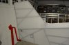
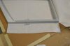
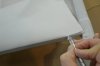
Tail Feathers.
All five are rib stitched, so anti chafe tape was applied, a half inch longer on each end than the designated locations for the rib stitching
Stabilizers
Technique. Some are better than others. The end result may look the same, but some techniques make the job go faster and easier. After spending the better part of a day covering the rudder and one elevator, I tried some different techniques. The remaining three sections went faster.
The stabilizers use a plain piece of fabric rather than an envelope like the other three tail sections.
1. Lay the frame on the fabric so the hinge lines up with the seam in the center of the fabric. Cut out the openings for the hinge first, using the “H” cut. Than clamp the fabric tightly in place at the ribs on the hinge side. No glue is applied to the hinge side of the elevator
2. Make sure the top surface is up and the bottom surface is down so that the leading edge seam will be on the bottom side when finished.
3. Pull the fabric on the bottom snug and use the iron to preshrink it around the leading edge.
4. Cut the fabric in preparation for gluing. Then put a narrow bead of Poly Tac near the base of the leading tube the full length of the tube and pull the fabric snuggly into place. This will leave most of the fabric to be glued sticking straight up. I found this easier than trying to glue the full vertical width of the fabric to the tube at one time.
5. With the fabric now tacked, go back and glue the fabric in place in foot long sections, massaging it to get the glue smooth. Sometimes I slit the fabric in each section glued to make it easier. Then the usual touch up with the iron to set the glue.
6. The ends are easy. Pre cut the end pieces and glue them in to place.
7. After the glue sets up, trim with a razor or exacto knife. I replaced the blade after each cut. It is amazing how quickly it dulls
8. Touch up with an iron and the seam virtually disappears.
9. Flip it over and to the same thing to secure the top piece in place, working from the bottom side.
Attachments
Similar threads
- Replies
- 17
- Views
- 14K
- Replies
- 16
- Views
- 6K